New Yorker FR-147 Скачать руководство пользователя страница 33

33

111079-01 - 12/20

FR

Installation & Service Manual

A.  WATER BOILERS:

1.


Filling of boiler and system.


GENERAL 

— 

In a hot water heating system, 

the boiler and entire system (other than the 

expansion tank) must be full of water for 

satisfactory operation. Water should be added 

to the system until the boiler pressure gauge 

registers 12 psi. To insure that the system is 

full, water should come out of all air vents when 

opened.

2.  BOILING OUT OF BOILER AND SYSTEM

.

 The 

oil and grease which accumulate in a new hot 

water boiler can be washed out in the following 

manner:
a.  Remove relief valve using extreme care to 

avoid damaging it.

b.  Add an appropriate amount of 

recommended boil out compound.

c.  Replace relief valve.
d.  Fill the entire system with water.
e.  Start firing the boiler.
f.  Circulate the water through the entire 

system.

g.  Vent the system, including the radiation.
h.  Allow boiler water to reach operating 

temperature, if possible.

i.  Continue to circulate the water for a few 

hours.

j.  Stop firing the boiler.
k.  Drain the system in a manner and to a 

location that hot water can be discharged 

with safety.

l.  Remove plugs from all available returns 

and wash the water side of the boiler as 

thoroughly as possible, using a high-

pressure water stream.

m. Refill the system with fresh water.

3.  Add appropriate boiler water treatment 

compounds as recommended by your 

qualified water treatment company.

4.  Make pH or Alkalinity Test.
  After boiler and system have been cleaned 

and refilled as previously described, test the 

pH of the water in the system. This can easily 

be done by drawing a small sample of boiler 

water and testing with hydrion paper which 

is used in the same manner as litmus paper, 

except it gives specific readings. A color chart 

on the side of the small hydrion dispenser 

gives the reading pH.  Hydrion paper is 

inexpensive and obtainable from any chemical 

supply house or through your local druggist. 

The pH should be higher than 7 but lower 

than 11. Add some of the washout chemical 

(caustic soda), if necessary, to bring the PH 

within the specified range. 

5.  Boiler is now ready to be put into service.

B.  EXCESSIVE MAKE-UP WATER
 

A leaky system will increase the volume of 

make-up water supplied to the boiler, which can 

significantly shorten the life of the boiler. Entrained 

in make-up water are dissolved minerals, salts 

and oxygen. When the fresh, cool make-up 

water is heated in the boiler, the minerals fall 

out as sediment, the salts coat the inside of the 

boiler, and the oxygen escapes as a gas. The 

accumulation of sediment eventually isolates the 

water from contacting the cast iron. When this 

happens the cast iron in that area gets extremely 

hot and eventually cracks. The presence of free 

oxygen or chloride salts in the boiler corrodes the 

cast iron from the inside. More make-up water and 

higher concentrations of contaminants damage 

the boiler sooner.  Our warranty does not cover 

corrosion and sediment-related damage.  Clearly 

it is in everyone’s best interest to prevent this type 

of failure. You can do your part by ensuring that 

your system is leak-free, keeping leakage to less 

than 2 percent of the boiler water volume each 

month.  Refer to Chart below.
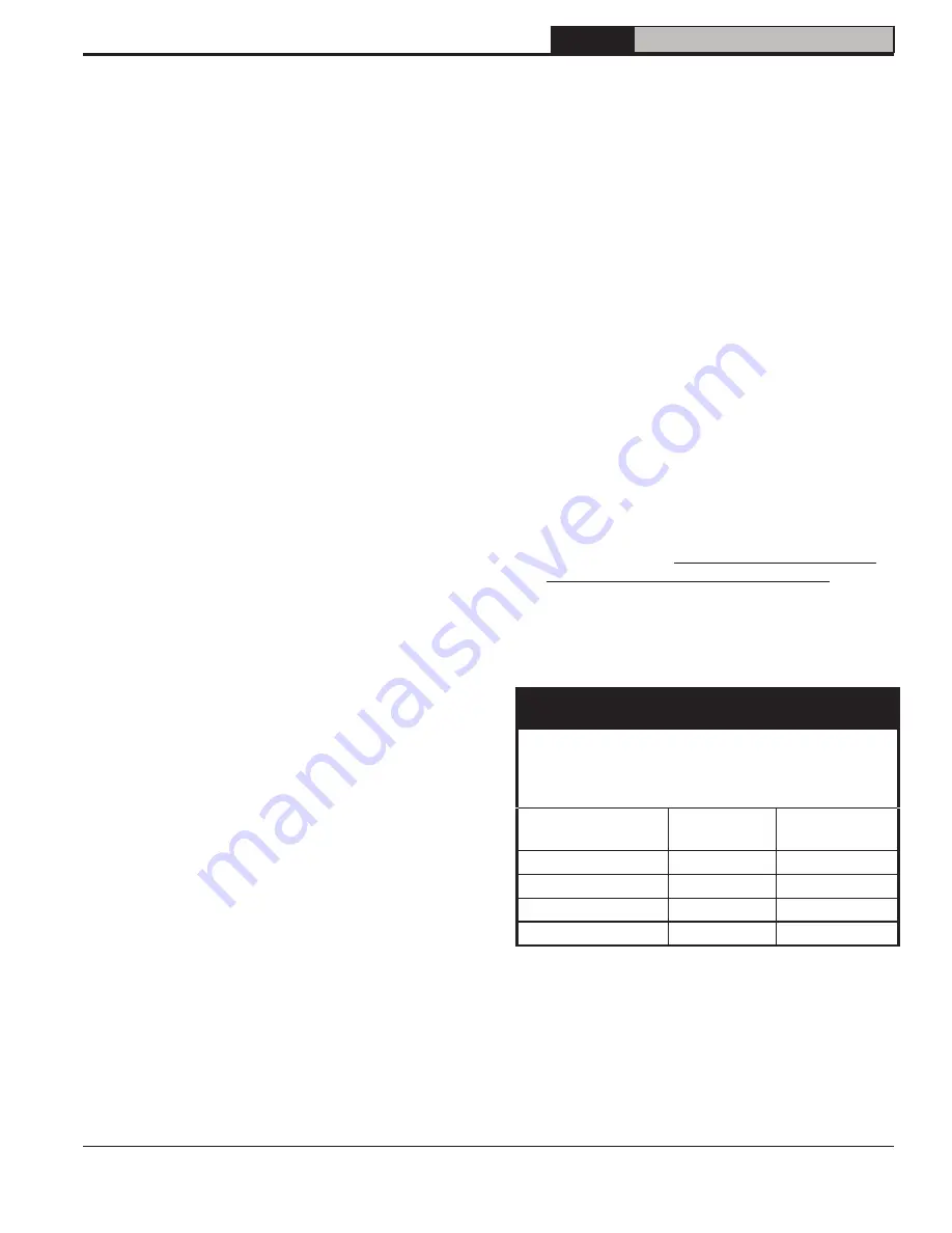
IMPORTANT

IMPORTANT

IF,  DURING  NORMAL  OPERATION,  IT  IS NECESSARY  
TO  ADD  MORE  WATER  THAN INDICATED  BELOW,  
CONSULT A  QUALIFIED SERVICE  TECHNICIAN  
TO  CHECK  YOUR SYSTEM  FOR  LEAKS.

Boiler Series

Gallons Per 

Month

Gallons Per 

Year

FR-HGS

0.2

2.4

FR-122

0.4

4.8

FR-147/173

0.8

9.6

FR-205/232

0.9

10.8

C.  ATTENTION TO BOILER WHILE NOT IN 

OPERATION
1. IMPORTANT
  IF BOILER IS NOT USED DURING WINTER 

TIME, IT MUST BE FULLY DRAINED TO 

PREVENT FREEZE DAMAGE.

2.  Spray inside surfaces with light lubricating or 

crankcase oil using gun with extended stem so 

as to reach all corners.

10

 Maintenance and Service Instructions 

Содержание FR-147

Страница 1: ...ng contractor When seeking information on boiler provide Boiler Model Number and Serial Number as shown on Rating Label Manual Contents Page 1 General Information 5 2 Pre Installation 7 3 Knockdown Bo...

Страница 2: ...operations of controls and safety devices operations of controls and safety devices D All wiring on boilers installed in the USA shall be made in accordance with the D All wiring on boilers installed...

Страница 3: ...stall Limit Sensor may result in property damage personal injury or loss of life due to elevated operating temperatures and or pressures This boiler is NOT suitable for installation on combustible flo...

Страница 4: ...chimney flue must be inspected and cleaned before the start of the heating season for any obstructions A clean and unobstructed chimney flue is necessary to allow noxious fumes that could cause injur...

Страница 5: ...01 12 20 FR Installation Service Manual Figure 1A FR HGS Water Boiler Heat Only Beckett Burner Figure 1B FR 122E Thru FR 232 Water Boiler With or Without Tankless Heater Beckett Burner 1 General Info...

Страница 6: ...Boiler Series Boiler Model Burner Capacity Heating Capacity MBH 2 Net Ratings Water MBH 3 AFUE Minimum Chimney Requirement GPH MBH 1 Round In Dia Rectangle In x In Height Ft FR HGS FRHGSL 0 80 112 100...

Страница 7: ...e Installation of Oil Burning Equipment NOTE 2 FR Series boilers can be installed in rooms with clearances from combustible material as listed above Listed clearances cannot be reduced for alcove or c...

Страница 8: ...ommunicating with the outdoors Locate one opening within 12 inches of top of space Locate remaining opening within 12 inches of bottom of space Minimum dimension of air opening is 3 inches Size each o...

Страница 9: ...lly insert limit sensor into immersion well such that the tip on the limit sensor touches the bottom of the immersion well See Figure 3 1 3 Mount burner to front fire door and wire according to instru...

Страница 10: ...Burner Spec Label Riello Burners 111083 01 5 Energy Guide Label 6 Limit Sensor Insertion Depth Warning Label 103106 03 7 ASME Cover Plate Label 81460041 Notes 1 Installation is Not complete unless al...

Страница 11: ...11 111079 01 12 20 FR Installation Service Manual Figure 3 4 Burner Mounting 3 Knock Down Boiler Assembly continued...

Страница 12: ...iping must be considered a If this boiler is used in connection with refrigeration systems the boiler must be installed so that the chilled medium is piped in parallel with the heating boiler using ap...

Страница 13: ...osition Installation of the relief valve must be consistent with ANSI ASME Boiler and Pressure Vessel Code Section IV WARNING Installation is NOT complete unless a safety relief valve is installed as...

Страница 14: ...14 111079 01 12 20 FR Installation Service Manual Figure 4 2 Recommended Water Piping for Circulator Zoned Heating Systems 4Water Piping and Trim continued...

Страница 15: ...15 111079 01 12 20 FR Installation Service Manual Figure 4 3 Recommended Water Piping for Zone Valve Zoned Heating Systems 4Water Piping and Trim continued...

Страница 16: ...articularly to well water An appropriate water softener should be installed based on the analysis and dealer s recommendation This is not only beneficial to the tankless heater but to piping and fixtu...

Страница 17: ...has been insulated and fitted with storm windows so that the heat loss of the home has been reduced This requires less fuel to be burned and sends 5Venting less heat up the chimney A new boiler proba...

Страница 18: ...vice Manual Figure 5 2 Draft Regulator Locations 5Venting continued c For the same reasons as in 2 above heat extractors mounted into the breeching are not recommended 3 For minimum clearances to comb...

Страница 19: ...ater pipes lighting fixtures television rays of the sun or near a fireplace Keep large furniture away from thermostat so there will be free movement of room air around this control Connect the thermos...

Страница 20: ...20 111079 01 12 20 FR Installation Service Manual Figure 6 1 Schematic Wiring Diagram without Tankless Heater Cold Start Control Beckett Burner 6 Electrical continued...

Страница 21: ...ly recommended B SINGLE PIPE OIL LINES 1 Standard burners are provided with single stage 3450 rpm fuel units with the bypass plug removed for single pipe installations Figure 7 1 Single Pipe Installat...

Страница 22: ...0 4 63 100 5 57 100 6 52 100 7 47 100 8 42 100 9 36 100 10 31 100 11 26 100 12 21 83 13 62 14 41 Table 7 2 Single Stage Units 3450 RPM Two Pipe Systems Table 7 3 Two Stage Units 3450 RPM Two Pipe Syst...

Страница 23: ...ed of air close zone valve or shut off valve Open zone valve to the next zone to be purged Repeat this step until all zones have been purged At completion open all zone valves i Close purge valve cont...

Страница 24: ...rner to run until oil flows from vent fitting in a SOLID stream without air bubbles for approximately 10 seconds 3 Close vent fitting and burner flame should start immediately after prepurge is comple...

Страница 25: ...be placed in a purge routine by See Figure 8 1 and Table 14 1 at the rear of this manual 4 ADJUST DRAFT REGULATOR for a draft of 0 02 water gauge over the fire after chimney has reached operating temp...

Страница 26: ...26 111079 01 12 20 FR Installation Service Manual Figure 8 2 L1 and V1 Head Electrode Positioning and Gun Setting Beckett AFG 8 System Start Up continued...

Страница 27: ...of unburned oil in the combustion area the control can only be reset three times The reset count returns to zero each time a call for heat is successfully completed v T T Jumper Select models have pre...

Страница 28: ...stance Reset safety switch Close line switch to boiler If burner starts and runs beyond safety switch cut off time cell is good If not install new cell Close hand valve in oil supply line Failure occu...

Страница 29: ...e systems 5 Recommended setting for Five zone systems HI Provides highest level of fuel savings E Optional Features NOTE The Program Mode Pro isaccessedbyturningtheLPTEMPdialtoa position just above OF...

Страница 30: ...l vs Standard Immersion Well When used to replace older temperature only controls the HyrdroStat can be installed on the existing well The Hydrolevel Elctro Well is required to activate low water cut...

Страница 31: ...Y to reset all features to the default settings 4 Reset LO TEMP and HI TEMP settings to desired temperatures 9 LED Legend and Test Settings Button a TEMP ACTIVE Indicates that the Fuel Smart HydroSta...

Страница 32: ...l the boiler temperature drops below the differential set point at which point the boiler will be allowed to fire again See Differential explanation NOTE This LED illuminates regularly during normal b...

Страница 33: ...reading pH Hydrion paper is inexpensive and obtainable from any chemical supply house or through your local druggist The pH should be higher than 7 but lower than 11 Add some of the washout chemical c...

Страница 34: ...nstructions outlined in Section IV Paragraphs A through K 10 Maintenance and Service Instructions continued WARNING This boiler contains controls which may cause the boiler to shut down and not restar...

Страница 35: ...brush clean front tube sheet Use care not to damage the insulation on the inside of the flue box Remove debris and vacuum as necessary e Replace turbulators and flue box door f Disconnect vent pipe f...

Страница 36: ...36 111079 01 12 20 FR Installation Service Manual Figure 11 1 Cleaning of FR Boiler 11 Boiler Cleaning continued...

Страница 37: ...sified as hazardous wastes in the United States and Canada First Aid Procedures If contact with eyes Flush with water for at least 15 minutes Seek immediate medical attention if irritation persists If...

Страница 38: ...t an air leak can have on CO2 readings 5 DIRT A fuel filter is a good investment Accidental accumulation of dirt in the fuel system can clog the nozzle or nozzle strainer and produce a poor spray patt...

Страница 39: ...tor relay is stuck closed see note below 2 Burner control will light then shut down after a short time then restart after one 1 minute a CAD cell is defective b Air leaking into oil line causing flame...

Страница 40: ...are illuminated and the control is installed on a standard immersion well this is false reading caused by a loss of continuity between the sensor and the inside of the well tube Follow steps 1 and 2 a...

Страница 41: ...l times when the control is powered Check for 120 VAC on terminals L1 and L2 YES Is the Red LED LOW WATER On YES NO Is the Yellow LED HI TEMP On YES The Control is Sensing High Temperature The burner...

Страница 42: ...ntinue to fire when there is a call from the thermostat or external zone Is the External Zone ZC ZR Calling for Heat YES The Control is Operating Normally NO Is the Low Limit Dial NO Set to OFF Check...

Страница 43: ...rker Wholesale distributor Should you require assistance in locating a New Yorker distributor in your area or have questions regarding the availability of New Yorker products or repair parts please co...

Страница 44: ...Installation Service Manual NOTE When ordering parts always give the serial number and model number shown on the boiler Also provide the name of the part s shown below FR Bare Boiler Repair Parts 13 S...

Страница 45: ...urner Door Assembly Includes Hardware N 109 111121 01 1 N 112 1 N 125 111123 01 1 1 N 132 1 1 1E Turbulator N 109 111125 01 11 N 112 12 N 125 18 18 N 132 111128 01 18 18 1F Combustion Chamber Insulati...

Страница 46: ...Stat 3250 Plus Cold Start 111133 01 1 1 1 1 1 1 Warm Start 111134 01 1 1 1 1 1 Electro Well 3 4 NPT x 4 110556 01 1 1 1 1 1 1 Relief Valve Conbraco 10 407 05 30PSI Obtain Locally 1 1 1 1 1 1 6 Draft R...

Страница 47: ...9 0 65 x 60W Delavan Loose 1 10 0 140 FRHGS 1 00 0 85 x 60B Hago Installed 9 1 FR 122 FR 122E 1 00 V 1 1 69 0 85 x 60A Delavan Installed 9 0 0 170 FR 147 FR147 1 25 V 1 1 69 1 00 x 60B Hago Installed...

Страница 48: ...eturn piping as shown below LWCO Location Select the appropriate size tee using the LWCO manufacturer s instructions Often the branch connection must have a minimum diameter to prevent bridging betwee...

Страница 49: ...ided piping and wiring connections and instructions to allow for this application How to Test Shut off fuel supply Lower water level until water level is BELOW the LWCO Generate a boiler demand by tur...

Страница 50: ...50 111079 01 12 20 FR Installation Service Manual SERVICE RECORD SERVICE PERFORMED DATE...

Страница 51: ...51 111079 01 12 20 FR Installation Service Manual SERVICE RECORD SERVICE PERFORMED DATE...

Страница 52: ...52 111079 01 12 20 FR Installation Service Manual...

Отзывы: