background image


LabLynx User Manual   Revision 1.1  2/18/2021


14


Using Cheetah with LabLynx 

Open Cheetah and select the appropriate configuration file for your setup. Open 
Cheetah.cfg using a text editor like Notepad or + and check that the Acquisition 
System Setup has LabLynx.cfg uncommented as seen below. A line in a .cfg file is 
uncommented by deleting the # at the start of the line. 


Figure 4-4 Uncomment LabLynx.cfg 


Select a channel configuration compatible with your setup by uncommenting the 
appropriate line. In the example below, the system is setup for 32 channels. A CSC 
(Continuously Sampled Channel) setup will plot 32 channels on the display. 
 

Содержание LabLynx

Страница 1: ...ralynx Inc 105 Commercial Drive Bozeman MT 59715 Phone 406 585 4542 Fax 866 585 1743 www Neuralynx com Revision 1 1 support Neuralynx com 2 18 2021 LabLynx User Manual Portable Digital Acquisition Sys...

Страница 2: ...ess 11 Enable Jumbo Packets 13 Using Cheetah with LabLynx 14 Start Cheetah and Turn LabLynx On 16 Connect LabLynx to Test Setup 16 Test the LabLynx with a Test Input Signal 17 Troubleshooting 20 Chann...

Страница 3: ...fg File Text 33 SetDigitalIOBit 34 Example cfg File Text 34 GetDigitalIOPortValue 35 Example cfg File Text 35 SetDigitalIOPortValue 35 Example cfg File Text 35 GetTransmittedChannels 35 Example cfg Fi...

Страница 4: ...2 3 and 4 Switches Up Reference Switch Down 17 Figure 4 7 Bank 2 3 and 4 Switches Up Bank 1 and Reference Switches Down 17 Figure 4 8 Bank 3 and 4 Switches Up Bank 1 2 and Reference Switches Down 18 F...

Страница 5: ...he Neuralynx mux headstage and transmitted wirelessly from the LabLynx Wireless communication uses 5 GHz WiFi 802 11 ac Features Wirelessly transmit up to 256 channels Record up to 256 channels to mic...

Страница 6: ...put Four 4 40 mounting holes Figure 3 1 LabLynx Base Battery Charger A grounded mini USB to barrel connector cable adapter necessary to charge the batteries of the LabLynx while device is in use 5 V p...

Страница 7: ...nal products to support the assembly and use of the LabLynx Digital Multiplexing mux Headstages Digitize neural signals at the headstage Reduce the wire count weight size and cost of the tether 30 kHz...

Страница 8: ...ance Plug Provides different resistance values in banks of 8 for multiple testing applications on 32 64 channel multiplexing mux headstages Figure 3 8 HS 36 mux Impedance Plug 2 Pin to BNC Cable Conne...

Страница 9: ...requires Cheetah 6 4 or later LabLynx supports up to 256 channels The number of channels that can be viewed and recorded in Cheetah depends on the Cheetah license If you need to change the order of a...

Страница 10: ...e PC through the wireless access point It is recommended that the Ruckus Router wireless access point be mounted on the ceiling for best performance Figure 4 1 Steps to Connect Access Point to PC Step...

Страница 11: ...static IP address must be set for the network interface that is used to connect to the wireless access point To set the static IP address go to Control Panel Network and Internet Network and Sharing C...

Страница 12: ...LabLynx User Manual Revision 1 1 2 18 2021 12 Set the IP information as shown below Figure 4 3 Computer IP Address Settings...

Страница 13: ...21 13 Enable Jumbo Packets In the properties window see Figure 4 2 Network Interface Properties above click the Configure button and then go to the Advanced tab Select the Jumbo Packet property and se...

Страница 14: ...that the Acquisition System Setup has LabLynx cfg uncommented as seen below A line in a cfg file is uncommented by deleting the at the start of the line Figure 4 4 Uncomment LabLynx cfg Select a chan...

Страница 15: ...LabLynx User Manual Revision 1 1 2 18 2021 15 Figure 4 5 Setting Channel Configuration...

Страница 16: ...otup Therefore headstages must be connected to the LabLynx before turning the LabLynx on Headstages connected after bootup will not function Connect LabLynx to Test Setup Step Description 1 Set the Mi...

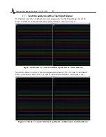
Страница 17: ...all 64 CSCs to 1000 V Each should show approximately 1 mVPP sine waves Figure 4 6 Bank 1 2 3 and 4 Switches Up Reference Switch Down Switch the Bank 1 switch to the Ground position down CSCs 1 8 and...

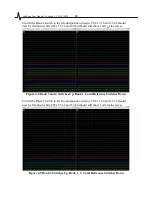
Страница 18: ...17 32 and 49 64 should still show 1 mVPP sine waves Figure 4 8 Bank 3 and 4 Switches Up Bank 1 2 and Reference Switches Down Switch the Bank 3 switch to the Ground position down CSCs 1 24 and 33 56 sh...

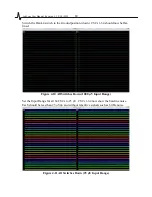
Страница 19: ...n CSCs 1 64 should now be flat lined Figure 4 10 All Switches Down 1000 V Input Range Set the Input Range for all 64 CSCs to 25 V CSCs 1 64 now show the baseline noise Each should be less than 25 Vpp...

Страница 20: ...osition up Each should be less than 25 Vpp and without repetitive signals such as 60 Hz noise Figure 4 12 All Switches Up 25 V Input Range Troubleshooting If Cheetah does not receive data after starti...

Страница 21: ...plexing headstages do not require channel mapping However some headstages particularly custom headstages may require channel mapping to properly correlate the headstage input channel numbering with Ch...

Страница 22: ...LabLynx User Manual Revision 1 1 2 18 2021 22 Hardware Overview Enclosure Figure 5 1 Enclosure Front View Figure 5 2 Enclosure Flipped View...

Страница 23: ...be used to either drive a stimulus current or a FLED uDB 25 connector 1 stimulus lines are routed to the 10 pin connector so that it can be driven with the Modular FLED driver See 5 1 2 10 pin Connect...

Страница 24: ...LabLynx User Manual Revision 1 1 2 18 2021 24 Figure 5 5 Connector 3 Pinout Figure 5 6 Connector 4 Pinout...

Страница 25: ...nnector 1 if the FLED Driver or Ultrasonic microphone are not in use Figure 5 7 10 pin Connector Pinout 24 pin Connector The 24 pin connector utilizes a 0 10 pitch 3M connector It is the primary locat...

Страница 26: ...tem Parameter Update The LED blinks blue when the LabLynx is updating its parameters using system_parameters txt on the microSD card 5 1 4 2 Error Codes 5 1 4 2 1 Invalid Network Name SSID The LED cha...

Страница 27: ...erated while the batteries are being charged The provided charging cable creates a grounded mini USB interface If the provided charging cable is not used to charge batteries while device is in operati...

Страница 28: ...Digital Converter Each channel is digitized on the mux headstage using a fixed reference The channels are AC coupled and the gain is fixed at 192 V V Each analog to digital converter is 16 bit and can...

Страница 29: ...ts interface can be accessed via a web browser The IP address for an access point received from Neuralynx is 192 168 4 1 The PC accessing this IP address should be on the same subnet 192 168 4 xxx The...

Страница 30: ...w wireless networks available in your area The screenshots below are from WiFi Analyzer on Android The picture below shows 5 GHz networks in the area You can see the LabLynx wireless network with SSID...

Страница 31: ...2021 31 Figure 5 10 Login Page using Microsoft Edge Under the Configuration list click Radio 5G Select the clearest channel you found using your network analyzer and then click the Update Settings but...

Страница 32: ...figure and query the device Commands can be sent by opening cfg files containing commands or by using the Neuralynx Netcom API Each command includes example text for executing the command within a cfg...

Страница 33: ...r base GPIO bits 4 7 for base GPIO 0 3 Lower 4 bits are for AFE GPIO bits 0 3 for AFE GPIO 0 3 Examples 00000000 all outputs SendBinaryCommand AcqSystem1 0100020500 11110000 base GPIO are inputs AFE G...

Страница 34: ...dBinaryCommand AcqSystem1 010003060300 24 pin GPIO 3 0 SendBinaryCommand AcqSystem1 010003060400 10 pin GPIO 0 0 SendBinaryCommand AcqSystem1 010003060500 10 pin GPIO 1 0 SendBinaryCommand AcqSystem1...

Страница 35: ...d all 4 GPIO on 10 pin connector 1 byte Upper 4 bits on 24 pin connector bits 4 7 for GPIO 0 3 on 24 pin Lower 4 bits on 10 pin connector bits 0 3 for GPIO 0 3 on 10 pin Examples list of command value...

Страница 36: ...onnector 1 and are highlighted in blue below Channels 65 128 come from Connector 2 and are highlighted in red below Channels 129 192 come from Connector 3 and are highlighted in green below Channels 1...

Страница 37: ...225 256 11111111 11111111 11111111 11111111 In the above example all channels are on Converting the above binary values into hexadecimal values gives the mask that will be included in the command FFFF...

Страница 38: ...FFFFFFFF FFFFFFFF SendBinaryCommand AcqSystem1 0100211AFFFFFFFFFFFFFFFFFFFFFFFFFFFFFFFFFFFFFFFFFFFFFFFFFFFFFFFFFFFFFFFF The above command must be on one line only the first channel enabled list of co...

Отзывы: