


FR-2RU-10-2
Rev.
8
17
5.5
Adding new module cards
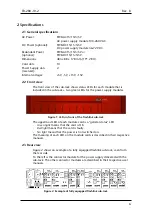
Figure 16: Overview of rear end of sub-rack showing blanks and connector modules
If a sub-rack is not fully equipped, there will be some unused card slots.
These slots have no connector modules, but a blank at the rear, as shown in
figure 16.
Modules are stacked from position #1 and up to position #10. In figure 16 the
next module shall be in position #3. The only exception is the GYDA-SC
controller, which shall
always
be in position #10.
Add modules by removing the blanks at the rear and replacing them with the
connector module for the new card. A blank has two screws, and a connector
module has four screws.
The copper finger strips around the edges of the connector modules and the
blanks ensure the EMC-shielding. Care should be taken when removing the
modules/blanks, so the finger strip is not torn off. This also applies when
inserting the modules / blanks.
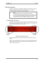
The connector modules with an optical interface have a rubber plug inside
each connector case to protect from dust. This rubber plug must be removed
before the module cards are inserted.
After the connector modules are mounted, the module cards can be inserted
as described in section 5.3.
Figure 17: Removing the rubber plug from module cards.