background image

NTI UNIMUX MULTI-USER KVM SWITCH 


35


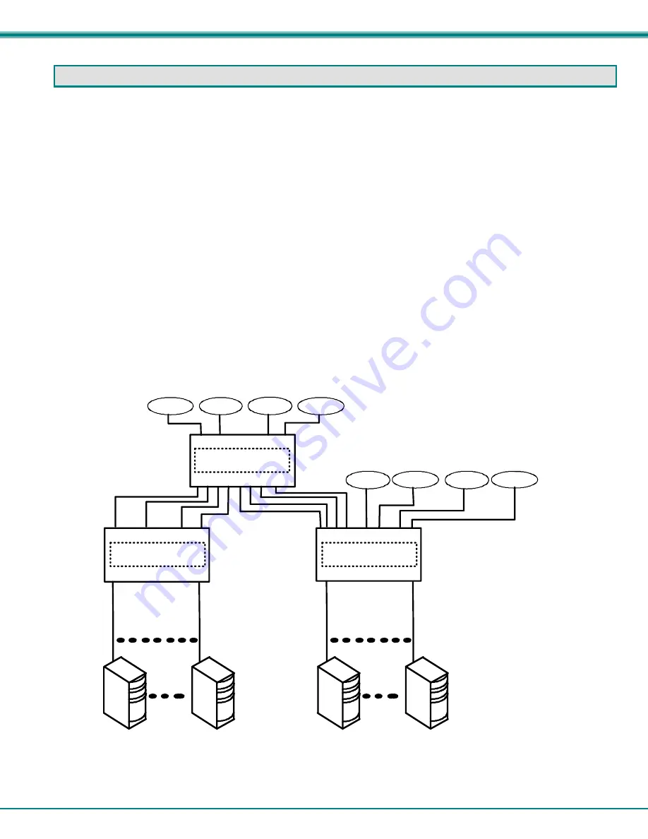
CASCADING 


The UNIMUX USB Matrix switch can be expanded to access up to 1024 CPUs by cascading multiple units together.  As many 
switches as there are CPU ports may be connected to a UNIMUX USB Matrix switch.   (See Figure 36) All downstream switches 
are referred to as "slaves" in a cascaded system.  The only additional hardware required to cascade switches is a set of device 
and monitor cables for each “SLAVE UNIT” (see MATERIALS on page 2).


All CPUs and switches can then be controlled by 

users using OSD commands with Command Mode.  

Limitations 

The front panel keypad is only used to operate standalone switches.   To control a cascaded network of switches, only the OSD 
commands within Command Mode will be recognized.  

The Matrix Switcher's Control Program (page 32) cannot be used to control cascaded switches.   It can only be used with a 
standalone switch.  

RS232 control (page 29) cannot be used between cascaded switches.    RS232 control can only be used between standalone 
switches.  

Users connected to accessible ports on downstream slaves (i.e. ports not connected to the master) will not be able to control 
switches or CPUs connected upstream.    Only control over CPUs and slaves downstream from a user's connection point will be 
enabled.  (See Figure 36) 

Slaves connected downstream from a master must be switches with at least as many user ports as the master.   I.e.  If the master 
is UNIMUX-4X32, connected slaves can be any switch with 4 or more user ports.     

Exception:  If the master is a single user UNIMUX switch, slaves connected downstream can be any size multi-user 
UNIMUX switch  (see Figure 37).  


                                                   Figure 36- Cascading with only multi-user units 


USER 1

USER 2

USER 3

USER 4

USER 5

USER 6

CPU PORTS

USER PORTS

MASTER

  UNIMUX-4X8

UNIMUX-8X16

UNIMUX-4X8

SLAVE

SLAVE

CPU PORTS

CPU PORTS

USER PORTS

USER PORTS

CPU1

CPU 8

Users 5-8 only have access to CPUs 9-24.
Users 1-4 have access to all CPUs

USER 7

USER 8

CPU 9

CPU 24

USBVEXT-xx-MM

USBVEXT-xx-MM

(8 CABLES)

USBVEXT-xx-MM

(16 CABLES)

Содержание KVM Switch

Страница 1: ...MAN028 Rev 8 6 08 UNIMUX nXm U Multi user USB KVM Switch Installation and Operation Manual Software Version 2 1 UNIMUXTM Series ...

Страница 2: ...gn without reservation and without notification to its users FIRMWARE VERSION UNIMUX Firmware Version 2 1 Please Note This manual applies to UNIMUX nXm U with firmware version 2 1 and later This version number can be found in the splash screen viewed when the UNIMUX is first powered ON example shown on page 12 If no version is shown it is an earlier model UNIMUX nXm U with earlier firmware version...

Страница 3: ... 11 Initial startup 12 User Access Functions 12 Command Mode 12 Settings 14 OSD Settings 15 Find Mode 15 Help Mode 15 Scan Mode 16 Broadcast Mode 17 Sharing Mode 17 Normal Mode 17 F3 Display Information 18 Security 19 Enabling Security 19 Password and User Name 19 User Login 20 Additional OSD Modes Available With Security Enabled 20 Administration Menu 20 System Configuration 21 Port Configuration...

Страница 4: ...rating Cascaded Switches 38 SUN RAY SUPPORT 38 SAFETY STATEMENTS 39 CABLES 39 TROUBLESHOOTING 40 SPECIFICATIONS 40 INDEX 41 WARRANTY INFORMATION 41 TABLE OF FIGURES Figure 1 Mount Switch to a Rack 5 Figure 2 Install user monitor s 6 Figure 3 Install user devices mouse and keyboard 7 Figure 4 Use USB A A 5M to extend a device or a computer 7 Figure 5 Group user ports by like number 8 Figure 6 Group...

Страница 5: ...Administrator password menu 23 Figure 27 Change value of Idle Timeout 24 Figure 28 Change the value of OSD Blank Timeout 24 Figure 29 Alternate Command Hot Key selection window 25 Figure 30 Select Language menu 25 Figure 31 Security Configuration 26 Figure 32 Login screen with security disabled 26 Figure 33 Keyboard layouts 28 Figure 34 RS232 connection with Matrix Y 1 cable 29 Figure 35 Pinout of...

Страница 6: ...Rays USB CPUs see page 38 re SUN Ray support MAC USB CPUs Supported User Devices and Monitors USB keyboard with Windows layout USB keyboard with SUN layout USB keyboard with MAC layout USB Mouse up to 3 buttons USB IntelliMouse scrollwheel USB Hub Mouse Trak trackball Logitech Kensington and Microsoft Wheelmouse or Trackball on Mac CPUs with special drivers Logitech Cordless Elite Duo keyboard and...

Страница 7: ...nXm U Replace the n with either 2 4 or 8 Replace the m with either 8 16 24 or 32 The following list represents the available sizes that can be ordered UNIMUX 2X8 U UNIMUX 4X8 U UNIMUX 8X8 U UNIMUX 2X8 UDT UNIMUX 4X8 UDT UNIMUX 8X16 U UNIMUX 2X16 U UNIMUX 4X16 U UNIMUX 8X24 U UNIMUX 2X32 U UNIMUX 4X32 U UNIMUX 8X32 U MATERIALS Materials Supplied NTI UNIMUX nXm U Multi user USB KVM Switch IEC Power ...

Страница 8: ...hing RS232 interface cable from a CPU to control the functions of one or more switches 9 MONITOR x 15HD female connectors for connection of user monitors 10 VIDEO x 15HD female connectors for attachment of video cables from CPUs Front View of UNIMUX 1 2 NTI R Network Technologies Inc UNIMUX TM 1 2 3 CPU 4 5 6 USR 7 8 9 0 ESC ENTER MENU Rear View of UNIMUX 3 4 5 6 7 8 10 9 MONITOR 1 MONITOR 2 MONIT...

Страница 9: ...o each CPU preventing connected CPUs from locking up Any user device cable can be hot plugged Typically the LCD display indicates the CPU to which each user is connected 10 configurations can be saved in memory by the user for instant setup recall No dip switches or jumpers necessary to configure Video formats up to 1900X1200 can be displayed from all platforms Users can control the switch using t...

Страница 10: ...0 32 x3 4 screws supplied Each screw should be of sufficient length to go completely through the NTI mounting flange rack frame and fully engage all threads in the captive nut Be sure to tighten all mounting screws securely Do not block power supply vents in the NTI switch chassis if provided Be sure to enable adequate airflow in front of and behind the NTI switch Attach all cables securely to the...

Страница 11: ...cable end from each user monitor to the female 15HD ports labeled MONITOR x on the rear of the UNIMUX switch See Figure 2 Figure 2 Install user monitor s Rear View of UNIMUX MONITOR 1 MONITOR 2 MONITOR 3 MONITOR 4 VIDEO 1 VIDEO 2 VIDEO 3 VIDEO 4 VIDEO 5 VIDEO 6 VIDEO 7 VIDEO 8 VIDEO 9 VIDEO 10 VIDEO 11 VIDEO 12 VIDEO 13 VIDEO 14 VIDEO 15 VIDEO 16 USER 1 USER 2 USER 3 USER 4 R S 2 3 2 CPU 1 CPU 2 C...

Страница 12: ... Figure 3 Install user devices mouse and keyboard Figure 4 Use USB A A 5M to extend a device or a computer NTI NETWORK TECHNOLOGIES INCORPORATED Tel 330 562 7070 www nti1 com 1275 Danner Drive Fax 330 562 1999 R Aurora Ohio 44202 USB A A 5M USB DEVICE CPU USB KEYBOARD USB TYPE A MALE CONNECTOR USB TYPE A FEMALE CONNECTOR TO UNIMUX SWITCH Rear View of UNIMUX MONITOR 1 MONITOR 2 MONITOR 3 MONITOR 4 ...

Страница 13: ...6 Connect the 15HD male cable ends of a USBVEXT xx MM cable from the video port of the same CPU to a VIDEO x port of the UNIMUX switch with the same port number as the user device cable See Figure 6 Note Make sure the CPU is connected to a Keyboard port and a Video port with the same number See Figure 7 Ports for CPU 1 Connections Ports for CPU 2 Connections CPU 1 CPU 2 CPU 3 VIDEO 1 VIDEO 2 VIDEO...

Страница 14: ... MONITOR 4 VIDEO 1 VIDEO 2 VIDEO 3 VIDEO 4 VIDEO 5 VIDEO 6 VIDEO 7 VIDEO 8 VIDEO 9 VIDEO 10 VIDEO 11 VIDEO 12 VIDEO 13 VIDEO 14 VIDEO 15 VIDEO 16 USER 1 USER 2 USER 3 USER 4 R S 2 3 2 CPU 1 CPU 2 CPU 3 CPU 4 CPU 5 CPU 6 CPU 7 CPU 8 CPU 9 CPU 10 CPU 11 CPU 12 CPU 13 CPU 14 CPU 15 CPU 16 NTI NETWORK TECHNOLOGIES INCORPORATED Tel 330 562 7070 Fax 330 562 1999 1275 Danner Dr Aurora OH 44202 www nti1 c...

Страница 15: ...r entries ENTER Used following single digit entries Display next 4 users and the CPUs they are connected to See note below Display previous 4 users and the CPUs they are connected to See note below MENU The RS 232 menu is displayed This allows the baud rate to be set at 9600 4800 2400 or 1200 baud and the unit address to be set to 1 15 See RS 232 control on page 29 Activate Memory Function 10 memo...

Страница 16: ...ound green highlight for menu functions cyan or light blue for CPUs The scroll bar can be used by clicking on the corresponding up and down arrow above and below the scroll bar The mouse wheel may be used to move the selection bar The Shift key must be used to enter an uppercase letter within all OSD menus Clicking on a listed CPU while in Command Mode will connect the user that CPU Available func...

Страница 17: ...e first displayed port in the list will be the port the current user is connected to followed by the next seven consecutively numbered ports Alternatively the list may be sorted alphabetically press the letter O to toggle sort method The names of accessible ports are displayed with blue characters If Security is activated the access rights for the user logged in may not include all ports Names of ...

Страница 18: ... specific port Press any valid number from 1 1024 to connect to a desired port port Enter Increases the ports listed by 1 page Page Down Decreases the ports listed by 1 page Page Up Enter Change Settings menu T Toggle ports listed to view by port number or alphabetically by port name O letter not number Enable disable Scan Mode S Enable disable Broadcast Mode B Enable disable Sharing only availabl...

Страница 19: ...enu functions available from the keyboard Function Keystroke Open OSD Settings screen O Go to Broadcast list B Go to Scan list S Change the scan dwell time period Enter any value from 002 255 for more on this see Scan Mode page 16 T Enable Disable right mouse button click emulation with Apple 1 button mouse see Mouse Click Equivalents on page 27 for more R Exit from Settings menu and return to Mai...

Страница 20: ...and maneuver through a list of CPU names The CPU name best matching the characters typed is selected The list of CPUs may also be searched for a specific or similar name The Find Mode function is not case sensitive The following commands are valid when the search option has been invoked from Command Mode Function Keystroke Erase previous character in search name Backspace Add a character to the se...

Страница 21: ...ress A deselect all ports so that none are scanned press N find a specific port to either select or deselect press F then any alphabetical or numeric character to locate the desired port Figure 14 Scan List A port is skipped from the scan cycle if one of the following conditions is true the port is not in the Scan List the port is used by another user and sharing is not enabled Security Mode is en...

Страница 22: ...slowly when in Broadcast Mode less than 20 wpm and cannot use the Backspace key Note The mouse will be disabled while in Broadcast Mode To return to the Settings menu press Esc The broadcast selection list is automatically saved Sharing Mode To activate or deactivate Sharing Mode press H from the Command Mode menu The text shown in the menu see Figure 10 will toggle between Sharing N and Sharing Y...

Страница 23: ... system structure level by level This is most useful when cascading switches see Cascading page 35 The image above indicates that the CPU connected to this port is actually connected through port 1 of the master switch Level 1 and through port 6 of the slave connected to the master switch port 1 Level 2 See Figure 16 Figure 16 Port information system structure CPU UNIMUX SLAVE CPU PORTS USER PORTS...

Страница 24: ...in the user will be connected to the first CPU that is powered ON To enter Command Mode press Ctrl accent tilde key The OSD menu will automatically appear on the monitor Figure 18 Administrator s main menu The administrator will activate security after logging in by pressing A S S E see page 26 Once logged in follow the instructions on page 20 for setting up users and changing the password Once th...

Страница 25: ...the limitations as determined by the administrator Note If security is not enabled the message Press F1 to Autologin will appear in the login screen While security is disabled a standard user must press F1 see Figure 19 to enter Command Mode Only the administrator can login using the name and password when security is not enabled Additional OSD Modes Available With Security Enabled Administration ...

Страница 26: ...ick on the box associated with the port to place a check mark in the box Note If a port is configured as connected to a non MAC CPU but is in fact connected to a MAC CPU the mouse will still work as a generic mouse No special functions provided by software drivers will be available Note MAC mode must be enabled on any CPU ports that are connected to a CPU through an NTI ST C5USBV extender Function...

Страница 27: ...o be edited If no name is entered a default name userXX where XX is the user number will be entered N Open an edit field to insert a user password up to 15 characters in length If no characters are entered no password will be required for that user P Usable characters for Name or Password Upper and lower case characters can be used A Z 0 9 or Shift A Z Open an edit field to confirm the password by...

Страница 28: ...nd return to previous menu Changes made will be saved automatically Esc Figure 25 Access Control list Change Administrator Password To change the Administrator Password press C from the Administration menu The Admin Password menu see Figure 26 enables the administrator to change his password Two edit fields are available one for password the other for verify password The password can be up to 15 c...

Страница 29: ...lue see Figure 28 2 enter the desired value 000 255 minutes 3 press Enter to save it and move to the next field 4 press Esc to exit the System Configuration menu Figure 28 Change the value of OSD Blank Timeout Alternate Command Hot Key To enable the administrator to assign a key in addition to the accent tilde key to use with Ctrl to enter into OSD Command Mode an Alternate Command Hot Key option ...

Страница 30: ... CPUs this feature may have no effect A list of available languages is displayed and can be scrolled using the mouse scroll wheel and or up arrow down arrow Home and End keys Figure 30 Select Language menu To manually program a specific language select a language and press Enter or click the left mouse button To automatically detect the language of the keyboard select AutoDetect and press Enter or...

Страница 31: ...figuration If Security is disabled for the port the user is connected to and the user attempts to login to Command Mode with the command key the login screen will include the instruction Press F1 to Autologin With security disabled Autologin provides full access to all connected CPUs and all users except the administrator must use it to login When security is enabled Autologin is not available and...

Страница 32: ...ose R Alt R Alt R Option Alt Graph SB Alt Windows Logo Command Meta SB R Arrow SB R Arrow Power Suspend SB Space Bar L and R Left and Right keys when two keys are marked the same on a keyboard Mouse Click Equivalents To emulate a right button click using Apple 1 button mouse hold down the Command key while pressing the mouse button Note Right mouse button emulation must be enabled see Settings on ...

Страница 33: ...mand Key Enter Enter Ctrl Shift Shift Caps Lock Tab Esc Ctrl Alt Backspace Num Lock Alt F1 F2 F3 F4 F5 F6 F7 F8 F9 F10 F11 F12 Scroll Lock Pause Break Print Screen SysRq Application Key Windows Logo Key Windows Logo Key help home pg up pg dn F12 F11 F9 F10 F8 F7 F6 F5 F4 F3 F2 F1 esc Enter Enter Alt Graph Shift Shift Caps Lock Tab Esc Ctrl Alt Backspace Num Lock Help Stop Props Front Open Find Cut...

Страница 34: ... 232 control On the DB9 female connector pins 1 DCD 4 DTR and 6 DSR are shorted and pins 7 RTS and 8 CTS are shorted Therefore CPU handshaking is bypassed and TXD and RXD are the only active signals A straight through DB 9 cable not null modem will work for most CPUs To daisy chain multiple units connect a Matrix Y 1 cable sold separately between the CPU and the first switch and between each switc...

Страница 35: ... USER KVM SWITCH 30 Figure 35 Pinout of Matrix Y 1 cable Unit 1 Source 2 3 3 3 5 5 5 2 2 7 8 1 4 6 Jumper Jumpers Not connected to source connector Unit 2 9D Female 9D Male 9D Male Wiring Schematic of Matrix Y 1 cable ...

Страница 36: ...ature see below SS SW 01 CR Enable Autostatus feature see below GO SW OP CR go SW OP IP CR Report the User port that is connected to the CPU port GM SW 00 CR go SW OP IP CR all connections List all switch User port connections all User ports to all CPU ports If the first field is not a known command as listed above or SW field is different from the serial address programmed in the switch memory th...

Страница 37: ...that controls NTI matrix switches through an RS232 interface The Matrix Switcher s Control Program is included on the CD packaged with the UNIMUX The Matrix Switcher s Control Program is downloaded by clicking on the link Download Matrix Switcher s Control Program found on the webpage the opens when the CD is inserted into the CDROM drive To install the Matrix Switcher s Control Program after down...

Страница 38: ...ave the connections into switch memory bank b Restore I O Connections from Unit Memory restore the connections from switch memory bank c Change All Units Baud Rate 9600 COM1 change RS 232 Baud rate of all switches the current baud rate and serial port are displayed in parentheses d Reset Unit send a reset command to the switch This command does not function at this time e Reset All Units send an i...

Страница 39: ...ect an input to all outputs 5 Read single output read which input is connected to an output 6 Read unit size read how many inputs and outputs the unit has 7 Return to main menu go back to the MAIN OPTIONS menu The Setup Options main menu selection only needs to be executed if the switches baud rate or unit address have been changed from the factory defaults 9600 baud and unit address 1 When this o...

Страница 40: ... page 29 cannot be used between cascaded switches RS232 control can only be used between standalone switches Users connected to accessible ports on downstream slaves i e ports not connected to the master will not be able to control switches or CPUs connected upstream Only control over CPUs and slaves downstream from a user s connection point will be enabled See Figure 36 Slaves connected downstrea...

Страница 41: ...t get connected to the master can be connected to by users Users connected to a slave downstream from the master will control only the CPUs directly connected to that slave switch i e users 5 and 6 in Figure 37 can only control CPUs 25 40 USER 1 USER 2 USER 3 USER 4 USER 5 USER 6 UNIMUX 8X16 UNIMUX 4X8 SLAVE SLAVE CPU PORTS CPU PORTS USER PORTS USER PORTS CPU1 CPU 8 Users 5 8 only have access to C...

Страница 42: ...CPU 10 CPU 11 CPU 12 CPU 13 CPU 14 CPU 15 CPU 16 NTI NETWORK TECHNOLOGIES INCORPORATED Tel 330 562 7070 Fax 330 562 1999 1275 Danner Dr Aurora OH 44202 www nti1 com R REAR VIEW OF MASTER UNIMUX MONITOR 1 MONITOR 2 MONITOR 3 MONITOR 4 USER 1 USER 2 USER 3 USER 4 R S 2 3 2 CPU 16 NTI R MONITOR 1 MONITOR 2 MONITOR 3 MONITOR 4 USER 1 USER 2 USER 3 USER 4 R S 2 3 2 NTI R CPU 16 SLAVE 2 UNIMUX SLAVE 1 U...

Страница 43: ...stem is ready to operate If security mode is activated the login window will be displayed on the screen The update configuration function can be recalled at any time by entering into Command Mode and pressing the F5 key Note The front panel keypad is used to operate only standalone switches To operate a cascaded network of switches use only OSD commands from Command Mode see page 11 Note Matrix Sw...

Страница 44: ...t be performed by factory trained and authorized service personnel Only those items specifically identified in this manual if any may be adjusted by the user of this product and adjusted only as instructed in this manual CABLES NTI DESCRIPTION USBVEXT 3 6 10 VGA and USB extension USBVEXT 3 6 10 15 MM VGA and USB interface USB AA 5M Connect up to 5 cables in a series for up to 25 additional meters ...

Страница 45: ... into live outlet and powered ON Mouse only moves up and down on computer s connected to the switch through a ST C5USBV Extender Driver communication not correct between mouse and CPU Port set for non MAC mode Configure any CPU ports that have a ST C5USBV connected for MAC Mode operation see page 21 Mouse not working properly or at all with SUN or PS 2 CPU connected Driver communication not correc...

Страница 46: ...7 system configuration 21 Troubleshoot 40 USBVEXT xx MM cable 8 user access control 23 user configuration 22 user control methods 10 Please Note This manual applies to UNIMUX nXm U with firmware version 2 1 and later This version number can be found in the splash screen viewed when the UNIMUX is first powered ON example shown on page 12 If no version is shown it is an earlier model UNIMUX nXm U wi...

Отзывы: