ADC-SDI-CC
Rev. 3
DATE: 23 July 2008
Network Electronics AS, P.O.Box 1020, N-3204 Sandefjord, Norway. Tel.: +47 33 48 99 99 – Fax: +47 33 48 99 98
E-mail: [email protected] – Web: http://www.network-electronics.com/
Technical specifications are subject to be changed without notice.
8
4. Configuration and Setup
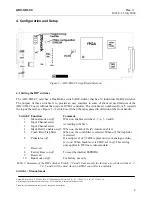
Figure 3 - ADC-SDI-CC simplified silkscreen.
he
DC-SDI-CC card, without the need of a GYDA controller. The switches are numbered from '1' towards
the
. A switc
the tap is placed in direction of the front handle.
Switch #
4.1 Setting the DIP switches
The ADC-SDI-CC card has a Dual-Inline switch (DIP-switch) that has 10 individual On/Off switches.
The purpose of these switches is to provide an easy interface to some of the most used features of t
A
top of the card, see Figure 3
h is
off
when
Function
Comment
1 Manual
mode
on
/
off
When
on
, enables switches 2, 3, 4, 5, 6 and 8.
2 Input Channel select
3
Input Channel select
According to Table 3.
4
Mark Field 1 enable
on
/
off
e
Mark Field 1
-feature enabled.
When
on
, th
5
Comb filter/Trap filter
When
on
, the comb filter is selected. When
off
, the trap filter
is selected.
6 Pedestal
on
/
off
ur analogue video,
t to
on
. When black level is 0 IRE, set to
off
. This setting
andard.
If a setup level of 7,5 IRE is present on yo
se
only applies to 525 lines video st
7 Reserved
8 Factory
Reset
on
/
off
To reset the internal EEPROM.
9 Reserved
10 Run
mode
on
/
off
For factory use only
Table 1: Summary of the DIP switches. Switch 7, 9 and 10 are mainly for factory use, while switches 1, 2,
3, 4, 5 and 6 will be used when no GYDA controller is available.
Switch 1 - Manual mode


