ADC-SDI-CC
Rev. 3
DATE: 23 July 2008
Network Electronics AS, P.O.Box 1020, N-3204 Sandefjord, Norway. Tel.: +47 33 48 99 99 – Fax: +47 33 48 99 98
E-mail: [email protected] – Web: http://www.network-electronics.com/
Technical specifications are subject to be changed without notice.
10
Switches 7 and 9 - Reserved
These switches are reserved and should always be in the
off
position.
Factory setting are switch 7 and 9 in
off
position.
Switch 8 - Reset to factory default
ADC-SDI-CC contains an EEPROM which stores the configuration of the card. Switch 8 can be used to
reset the EEPROM to the factory default. Follow the procedure described below.
Action Comment
1 Power
down.
2 Turn switch 8
on
.
Switch 1 must also be turned
on
for this to have effect.
3 Power up.
ADC-SDI-CC enters a special state where the EEPROM is restored to
factory default values. This is flagged by the Card State LED, which starts
to blink yellow.
4 Power
down.
5 Turn switch 8
off
.
If you want the DIP switches to be placed in the factory default position,
this is the time to do so: Switch 10 should, as always, be turned to the
on
position. Switch 1 may be turned
on
or
off
.
6 Power up.
The card EEPROM is now reset to factory settings.
Table 3: Method to restore the ADC-SDI-CC card to factory settings. Remember to let some seconds pass
by each time you power down, to allow capacitors to be fully discharged.
Switch 10 - Run mode
Switch 10 is purely used for service upgrade of the ADC-SDI-CC card. It should always be in the
on
position. If switch 10 is in the
off
position, the Card State LED will light up red, and the ADC-SDI-CC
card will enter programming mode. This causes no harm, but the card will not work in this mode.
Factory setting is switch 10 in
on
position.
4.2 Reset
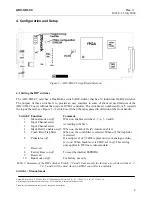
The push-button just behind the front LEDs is a reset switch, see Figure 3 . It has the same effect as a
power off – power on
cycle.


