N58 Hardware User Guide
Chapter 5 Application Interfaces
Copyright © Neoway Technology Co., Ltd. All rights reserved.
47
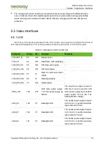
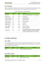
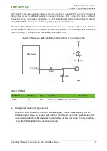
USIM2_DATA
22
B
USIM2
data
input/output
Connect this pin to USIM2_VCC by
using a 4.7 kΩ pull-up resistor.
USIM2_CLK
23
DO
USIM2 clock output
-
USIM2_RESET
24
DO
USIM2 reset
-
USIM2_DET
25
DI
USIM2 detection
-
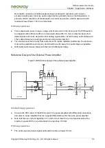
N58 provides two USIM card interfaces and supports dual USIM single standby. USIM1 is used by
default. Adaptive 1.8 V/3 V USIM cards are used. Figure 5-23 shows the reference design of USIM
card (with the hot plug function) interfaces.
Figure 5-23 Reference design of USIM card (with the hot plug function) interfaces
1uF
CLK
RST
VCC
VPP
GND
USIM Card
DATA
GND
DET
47k
Ω
VDD_1P8
USIM _DATA
USIM _CLK
USIM _RESET
USIM _VCC
USIM _DET
N58 Module
4.7k
Ω
C1
R5
C2
C3
C4
C5
C6
D1
20Ω
R1
20Ω
R2
20Ω
R3
20Ω
R4
D2
D3
D4
D5
R6
Schematic design guidelines:
USIM_VCC is the pin for supplying power only to USIM cards, and its maximum load capacity is
50 mA. USIM_VCC cannot be used to supply power to other loads.
Connect the USIM_DATA pin to USIM_VCC by using a 4.7 kΩ pull-up resistor in the external
design since the USIM_DATA pin is not pulled up internally.
USIM_CLK is the clock signal pin of the USIM card.
In applications with complex electromagnetic environments that have high requirements for ESD
protection, it is recommended to configure ESD protection components (with a junction
capacitance less than or equal to 7 pF) on each signal cable.
Connect a resistor with a resistance not greater than 20 Ω respectively to USIM_DATA,
USIM_RESET, USIM_CLK, and USIM_DET in series close to the card connector to enhance the
ESD performance.
C1-C5 are high-frequency filter capacitors on each signal cable, and the capacitance is less than
or equal to 10 pF.


