


N58 Hardware User Guide
Chapter 5 Application Interfaces
Copyright © Neoway Technology Co., Ltd. All rights reserved.
63
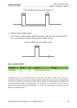
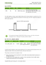
Over-current: If the current is greater than or equal to 45 mA or a short circuit occurs, the N58
module indicates that the antenna is in the over-current state.
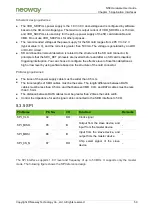
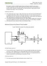
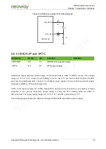
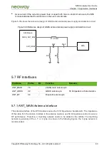
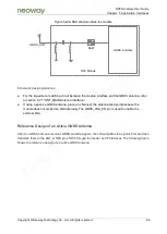
Figure 5-38 shows the reference design of GNSS active antenna power supply and detection circuit.
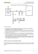
Figure 5-38 Reference design of GNSS active antenna power supply and detection circuit
N58 Module
SMA
ANT_GNSS
GNSS_ANT_BIAS
NC
NC
33pF
33pF
47~100nH
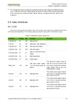
5.7 RF Interfaces
Pin Name
Pin No.
I/O
Function
Remarks
ANT_MAIN
76
-
2G/4G main antenna pin
50 Ω impedance characteristics.
ANT_GNSS
92
-
GNSS antenna pin
ANT_BT
94
-
Bluetooth antenna pin
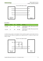
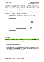
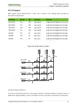
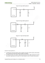
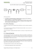
5.7.1 ANT_MAIN Antenna Interface
The antenna interface of the N58
module requires the 50 Ω impedance characteristic. The impedance
of the cable from the module interface to the antenna needs to use 50 Ω impedance control to ensure
RF performance. Therefore, a matching network needs to be added in the middle. The matching
network is generally of the L, T, or π type. As shown in the following figures, the π-type network is
recommended.