background image


6

Version: 9a 

13.11.2018

EN

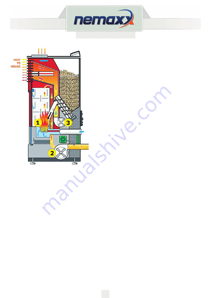
The heater is mainly made up of following items:
1. Combustion burn pot
2. Exhaust fan
3. Room circulation fan and auger motor.

The following is a list of main components and their 

functions:

IGNITER

The HEATER comes equipped with an automatic electric 

igniter for lighting the fuel when the heater is in lighting 
mode only. 

The igniter remains energized for the first eight minutes of 

the lighting sequence.

VACCUM SWITCH

The HEATER has a safety vacuum switch located behind 

the left door, fastened to the base. 

If a low pressure is created in the firebox by a leak, 
opening the front door, a blocked flue, or unsealed ash 
drawer, the vacuum switch will sense it and cause the 

heater to go into a shutdown mode.

AUGER AND AUGER MOTOR

The 2 RPM auger motor turns the auger lifting pellets up the auger tube. 


The pellets ed down a tube and into the firepot. The auger is controlled by the control board.

OVER TEMPERATURE THERMOSTAT

This safety switch is installed on the bottom of hopper and will shut off the heater if it senses 


excessive temperatures (70 degrees).

CONVECTION BLOWER THERMOSTAT

This switch is installed on the vent pipe and turns the convection blower on when the heater is 


above 40 degrees.

Содержание P6

Страница 1: ...Version 9a 13 11 2018 FREESTANDING PELLET STOVE P6 P9 and P12 ORIGINAL OPERATING INSTRUCTIONS EN THIS MANUAL MUST STAY WITH APPLIANCE 15 0036...

Страница 2: ...ld result in property damage bodily injury or even death Save these instructions INSTALLER THIS MANUAL MUST STAY WITH APPLIANCE TABLE OF CONTENTS 1 Fuel Requirement 3 2 Stove Features 4 3 Method of co...

Страница 3: ...t stove dealer for tested fuel and a list of monitored fuel manufacturers Using poor quality or prohibited pellet fuel will have a negative effect on the function of your pellet stove and can also lea...

Страница 4: ...85 100 Air inlet Pipe MM 50 50 50 Air outlet Pipe MM 80 80 80 Heating Performance range KW 3 8 11 5 3 9 3 6 Room heating capacity m3 dependent on house insulation M3 60 300 60 220 60 120 Consumption...

Страница 5: ...Side Panels 8 Chamber Insulation cover 9 Shoulder 10 Hot wind driver 11 Motherboard 12 Fire pot 13 Vacuum Switch 14 Igniter 15 Combustion fan 16 Blower 17 Rear Cover 18 Bottom Clear cover 19 Top clear...

Страница 6: ...r fastened to the base If a low pressure is created in the firebox by a leak opening the front door a blocked flue or unsealed ash drawer the vacuum switch will sense it and cause the heater to go int...

Страница 7: ...The flue system is based on negative pressure in the combustion chamber and a slight overpressure on the flue gas outlet It is therefore important that the flue gas connection is fitted correctly and...

Страница 8: ...y corners and bends If you cannot connect directly to the chimney use a connection piece with cleaning opening if possible For optimum efficiency please use the type of connector we recommend Horizont...

Страница 9: ...ed with an approx 2 m long connecting cable with a plug The cable must be connected to a 230 V 50 Hz electrical supply The average electric power consumption is approx 100 watts during heating During...

Страница 10: ...cm 2 inches For longer connection runs the diameter must be increased to approx 10 cm after approx 1 m The pipe should not be longer than approx 4m in total to guarantee adequate air feed and not hav...

Страница 11: ...leasant smell Please open the window and door for ventilation NOTE Before first usage it is necessary to put a handful of wood pellet to the fire pot NOTE The fire pot and underneath the fire pot must...

Страница 12: ...OPERATION USERS GUIDE Please operate the stove as following refer to stove structure figure and electrical control figure Check the box pellet grate bar ash pan then adjust to proper position OPERATIO...

Страница 13: ...loading in the burn pot This state remains up to when the smokes temperature doesn t exceed the planned threshold 3 When the Lighting phase is finished some minutes will be necessary for the flame st...

Страница 14: ...fire pot After that push to clear the word E2 Follow the above process to ignite and start again HOWEVER it is possible to switch off the heater in every functioning phase Turning off the heater is d...

Страница 15: ...s the selected power MINIMUM POWER P4 MEDIUM POWER P2 LOW POWER P3 MAXIMUM POWER P1 ECO STAGE If the room temperature exceeds the set temperature the stove is automatically stopped Eco1 or turns to mi...

Страница 16: ...RE SETTING Pressing the keys on the display the temperature can be selected How to Check the Room temperature Exhaust Smoke Temperature Safety Protection Temperature which is located under the hopper...

Страница 17: ...17 Version 9a 13 11 2018 EN HOW TO SET DETAILS SETUP QUICK REFERENCE GUIDE...

Страница 18: ...setup menu This procedure applies to all subsequent setting points COMBUSTION FAN S AND BLOWER S SPEED SETTING Press and hold the button approx 2 seconds to enter the setup menu The screen will displa...

Страница 19: ...ed to the exhaust fan s speed of the Cleaning stage The adjustable range is also from 20 to 20 The following is P6 this data is related to the exhaust fan s speed of the Feeding Lighting and minutes o...

Страница 20: ...e day or time To save the setting press and enter the next setting CLEANING SETTING Begin as described on page 18 Press until the following message appears You can adjust the time of cleaning during t...

Страница 21: ...g the switching on and the switching off at the pre fixed timetables You can program daily switching on and switching off for the whole week By keeping the key pushed you will find the attached instru...

Страница 22: ...ve To save the setting press and enter the next setting ECO MODE SETTING Begin as described on page 18 Press until the following message appears With you can choose Yes Or No Yes resets factory settin...

Страница 23: ...roken 4 The igniter is broken It means there is an earthquake during the opera tion time or the stove has been tilted Only for the Japanese version Problem with the temperature sensor Unplugged broken...

Страница 24: ...he Error code It means temperature sensor 1 exhaust gas temperature sensor short circuit It means temperature sensor 2 safety temperature sensor below the hopper short circuit It means temperature sen...

Страница 25: ...he 2 RPM auger motor turns the auger lifting pellets up the auger tube The pellets are then dropped down a tube and into the firepot The auger motor is controlled by the control board PROTECT TEMPERAT...

Страница 26: ...ng the pellets in the pellet container should they stick to the side walls Wood as a fertilizer Wood mineral residue approx 1 2 remains in the combustion chamber as ash This ash is a natural product a...

Страница 27: ...an fire pan daily If the stove is heated in continuous operation then it must be switched off twice within 24 hours in order to clean the pan danger of flash back EN CLEANING THE FIRE PAN Reassure tha...

Страница 28: ...e the loosened ash Clean these passageways only when the stove and ash are cold Do not start a fire in the vacuum cleaner by vacuuming up hot ash Side panels are located on both sides of the stove A s...

Страница 29: ...2018 EN Step 1 Remove the top cover s D f ex model P12 Step 3 Remove the cover D below and clean the access opening with brush and vacuum cleaner Step 2 Clean the access openings 3 and 5 Orientation...

Страница 30: ...30 Version 9a 13 11 2018 EN Left access opening Right access opening Step 4 Clean the access openings 1 and 2 regularly in the back upper part of the combustion chamber 1 2...

Страница 31: ...LEANING THE VENT PIPE Soot and Fly ash Formation and Need for Removal The products of combustion will contain small particles of fly ash that will collect in the exhaust venting system and restrict th...

Страница 32: ...32 Version 9a 13 11 2018 EN 7 TROUBLESHOOTING HOW TO REPLACE INGITION BAR AND AUGER SYSTEM HOW TO REPLACE THE ROOM FAN BLOWER...

Страница 33: ...33 Version 9a 13 11 2018 EN HOW TO REPLACE THE COMBUSTION FAN...

Страница 34: ...ttom If after stabilization it doesn t work there must be something wrong It is normal It will start automatically when the temperature is above 30 degrees on the venting pipe Please wait No power in...

Страница 35: ...t is normal Please be patient C Regarding the last stage Feed unit is blocked Check the auger is blocked or not There is a problem with the connection between motor and auger Check the screw between a...

Страница 36: ...ustion fan Cool the stove at least 1 hour then operate again or change the low temperature switch 30 C ECO its normal waiting after the temperature is below set on it will auto matically switch on aga...

Страница 37: ...can be powered with a gas driven electrical generator However the generator s electrical regulator may not be compatible with the stove s electronics The higher the quality of the generator the great...

Страница 38: ...8832 Wollerau Switzerland E Mail sales bargain24 ch Internet www bargain24 com REPRESENTATIVE eFulfillment GmbH Ikarusallee 15 30179 Hannover Germany The right to make technical and design modificatio...

Страница 39: ...39 Version 9a 13 11 2018 EN W Z h E E W h E W d E E t E s dms m E Z t K d E E E W D...

Страница 40: ...40 Version 9a 13 11 2018 EN K D Z t t t t d d E D...

Страница 41: ...41 Version 9a 13 11 2018 EN W Z h E E W h E W d E E t E s dms m E Z t K d E E E W D...

Страница 42: ...42 Version 9a 13 11 2018 EN K D Z t t t t d d E D...

Страница 43: ...43 Version 9a 13 11 2018 EN W Z h E E W h E W d E E t E s dms m E Z t K d E E E W D...

Страница 44: ...44 Version 9a 13 11 2018 EN K D Z t t t t d d E D...

Страница 45: ...45 Version 9a 13 11 2018 EN...

Страница 46: ...46 Version 9a 13 11 2018 EN...

Страница 47: ...47 Version 9a 13 11 2018 EN...

Страница 48: ...48 Version 9a 13 11 2018 EN...

Страница 49: ...49 Version 9a 13 11 2018 EN...

Страница 50: ...50 Version 9a 13 11 2018 EN...

Страница 51: ...51 Version 9a 13 11 2018 EN...

Страница 52: ...52 Version 9a 13 11 2018 EN...

Страница 53: ...53 Version 9a 13 11 2018 EN...

Отзывы: