


Wire the Mains cable into the terminal block. Provision has been made for this and identified as
the E (Earth), L1 (Live switched), L2 (Live permanent) and N (Neutral) terminals. There are two
pairs of contacts for each of these to facilitate a mains cable that can be looped in and out of
the unit, an identical terminal block is also available at the other end of the luminaire to allow
the unit to be through wired. The L2 terminals on a standard unit is not electrically connected
but allows them to be used on the same circuits as
emergency luminaires.
4.
Installer should earth the unit separately – an internal and external earth point are
provided as standard at each end of the luminaire
5.
Connect wires to mains supply.
6.
If the unit is opened for any reason, disconnect mains –
On emergency luminaires
there may be more than one mains supply
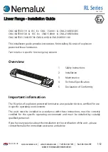
Typical wiring diagram - Emergency Variants
N
E
L1
L2
EARTHTOSCREW
PSU
PSU
WHITE/RED
WHITE
BLUE
BROWN
BLUE
BROWN
GREEN
RED
WHITE
TO LED's
Typical wiring diagram - Standard Variants
N
E
L1
L2
EARTH TO SCREW
PSU
WHITE/RED
WHITE
BLUE
BROWN
GREEN
TO LED's
BATTERY
RED
RED
BLACK
BLACK
FUSE
GREY
PSU
BLUE
BROWN
RED
WHITE
REMOVE LINK IF 4-CORE CABLE USED
Typical wiring diagram - Standard Variants
4
-
1
2
www.nemalux.com | [email protected] | Tel 403•242•7475 | Fax 403•243•6190
SUBJECT TO CHANGE WITHOUT NOTICE
MADE IN
UK


