11
t
848 Airport Road, Walla Walla, Washington 99362 U.S.A.
Tel: +1 509.525.7660 / Fax: +1 509.525.7907
twigwirelesscontrols.com
SYSTEM INFO & SETUP
Contains FCC ID: ZH6-VRCOMM-HP / Contains transmitter module IC: 9686A-VRCOMMHP
This device complies with Part 15 of the FCC Rules. Operation is subject to the following two conditions: (1) this device may
not cause harmful interference, and (2) this device must accept any interference received, including interference that may
cause undesired operation.
nelson Irrigation Corporation — Tel: +1 509.525.7660 — www.nelsonirrigation.com
Rev. 15 - 4/5/13
Press
to wake the display. Press
to advance to next menu.
MenU
DesCrIpTIon/aCTIon
signal strength
Good signal =
Poor signal =
solenoid Test
Press
to begin test.
Solenoid #1 closed. Press
to open.*
Solenoid #1 open. Press
to close.*
Press
to end test.
**
*
When multiple solenoids are controlled by one
TWIG
, press
and use or
to test each solenoid.
**After a solenoid test, the valve will return to its original state after several seconds.
Battery strength
Max charge =
Low battery =
TWIG ID
Press
to view the
TWIG
ID.
Press
to exit.
TWIG Driver network
Press
to view/confi gure current network.
Press
to exit. Press
to reset.
Press
to
search available networks.
Available networks displayed. Press
to join.
Join network countdown - display will return to
signal
menu
when fi nished.
radio Channel
Channel ID set by TWIG Driver
Press Enter to wake the display. Remember the radios are still working even when the display goes blank.
If the TWIG is not in a network then ‘none’ will display. If the TWIG is joined into a live network, the display
shows the ‘S’ followed by bars for radio signal. Maximum is six bars. The bars indicate how strong the
radio signal is between the TWIG and the TD200 controller.
Press the right arrow and the three letters -SOL- (SOL=solenoid) and the dash marks appear. The dashes
indicate an action is available. To test the solenoids, press ENTER. Arrow to the right to display the
solenoid number. Press
to switch the solenoid ON and
to switch the solenoid OFF. When finished
press ENTER to end test.
Press the right arrow. The bars displayed here indicate the voltage charge of the ‘D’ cell batteries in the
TWIG. Press the right arrow to see ID. Here the dashes indicate available information. Press ENTER. The
display shows the ID for this TWIG. This ID is in the TWIG memory and cannot be changed. Press ENTER
again to go back. Press the right arrow to see NET. Here the dashes indicate available information. Press
ENTER. The display shows the network ID.
3.6 SETTInG UP ThE TwIG In A nETwORK:
Start the TWIG network process by having power to the TD200. It is best to set the display dial to VIEW.
That way you can see the ID number of TWIGs that join. Go through the TWIG reset process explained
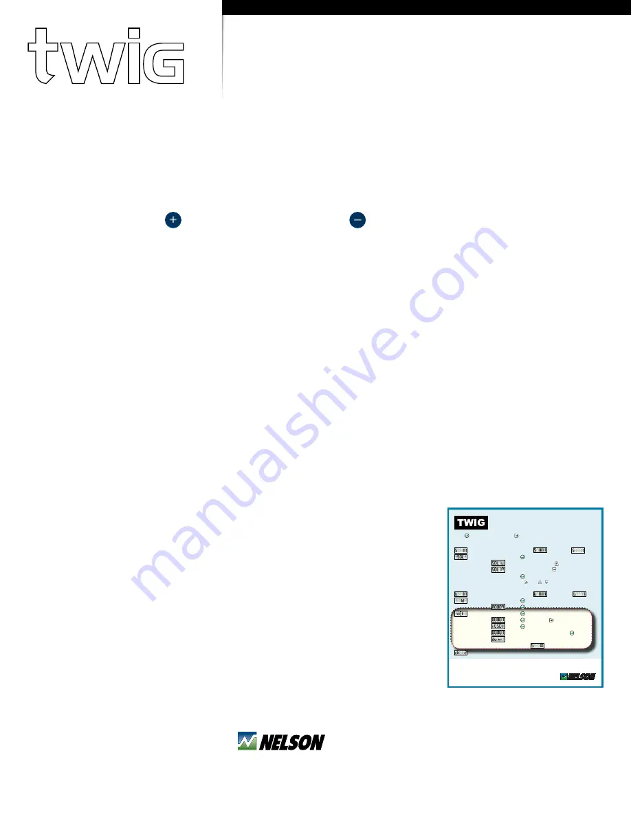
on the door card (sample is shown in Figure 3.4.2). The essential part of the TWIG setup is the highlighted
portion. If the display is blank then press ENTER to wake the display. Remember the radios are still
working even when the display goes blank.
Press the right arrow until you see NET. Press ENTER. If the TWIG is already in a network, the ID of the
networks TD200 will appear. If you want to join a new or different controller network, press the right
arrow and see RESET. Then press ENTER and the TWIG will begin a search to discover available TD200
controller networks. The TWIG can join only one network at a time. If there
are no networks available in the area, the word ‘Find’ will flash. When a
TD200 is discovered then its number will be displayed on the TWIG display
and remain for about 3 seconds. While the number you want is still on the
display, you must immediately press ENTER. During the joining process the
display will alternately flash “Join” and seconds remaining until it is done. If
you happen to miss the number you want then it will cycle back in a short
time so you can try again to select it. When done, the signal bars will appear
on the display. The TWIG has joined a network. Now you can press and hold
the plus button if you want to see the radio signal strength. The maximum
signal number possible is 84 and normally a number higher than 20 is
adequate.


