MagnaTrack S
GB
18
max.
45° 90°
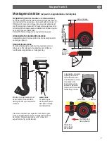
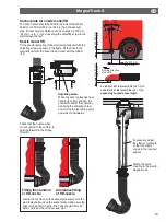
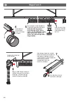
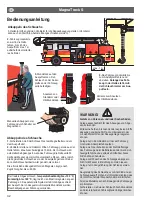
Locate the nozzle on to the exhaust pipe and secure
the electromagnetic unit on the anchor plate ma-
king sure the hose is tensioned correctly. The hose
should form a 90° bend coming out from the exhaust
pipe (see figure next page).
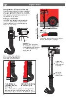
Check that the nozzle, when
not connected to the vehicle, is
pointing forward in the driving
direction.
Adjusting screw.
For adjusting the
spring power in the
nozzle after fitting the
anchor plate.
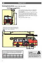
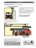
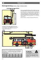
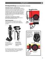
250 +/- 150 mm
(10 in +/- 6 in)
min. 200 mm (min. 7 3/4 in)
1000 +/- 200 mm (39 in +/- 6 in)
min. 300 mm (12 in)
Forward
direction of
vehicle.
Anchor plate for standard nozzle
The anchor plate should be fitted to the side of the vehicle
according to the measurements given in the figure.
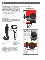
Mounting instructions
(exhaust pipe, anchor plate, nozzle )
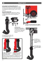
The exhaust pipe
(for standard- and HB-nozzle)
For best result, side mounted exhaust pipes should be posi-
tioned according to the figure and point at right angles to the
coachwork or a little backwards, yet not more than 45°. The
pipe should be straight and lie flush with or protrude slightly out
from the side of the vehicle. It is possible that modifications may
be required to the exhaust system of the vehicle to ensure the
optimum position of the exhaust pipe.
Standard nozzle
Fit the chain lock in the electromagnetic unit as shown in the
figure. Fit the hose in the electromagnetic unit with the hose
clip and cover with the rubber ring.
In the opening of the
standard nozzle there
are two landing (fric-
tion) pads, one made
of steel, the other of
rubber. The steel pad
must be in front of the
rubber pad when
viewed in relation to
the forward driving
direction of the
vehicle.
The steel pad
must be fitted
on this side.
Forward direction
of vehicle.
steel pad
rubber pad
Содержание MagnaTrack S
Страница 2: ...MagnaTrack S ...
Страница 91: ...MagnaTrack S 91 ...

