background image


NEC Versa P700 Disassembly Manual 

Page 27 

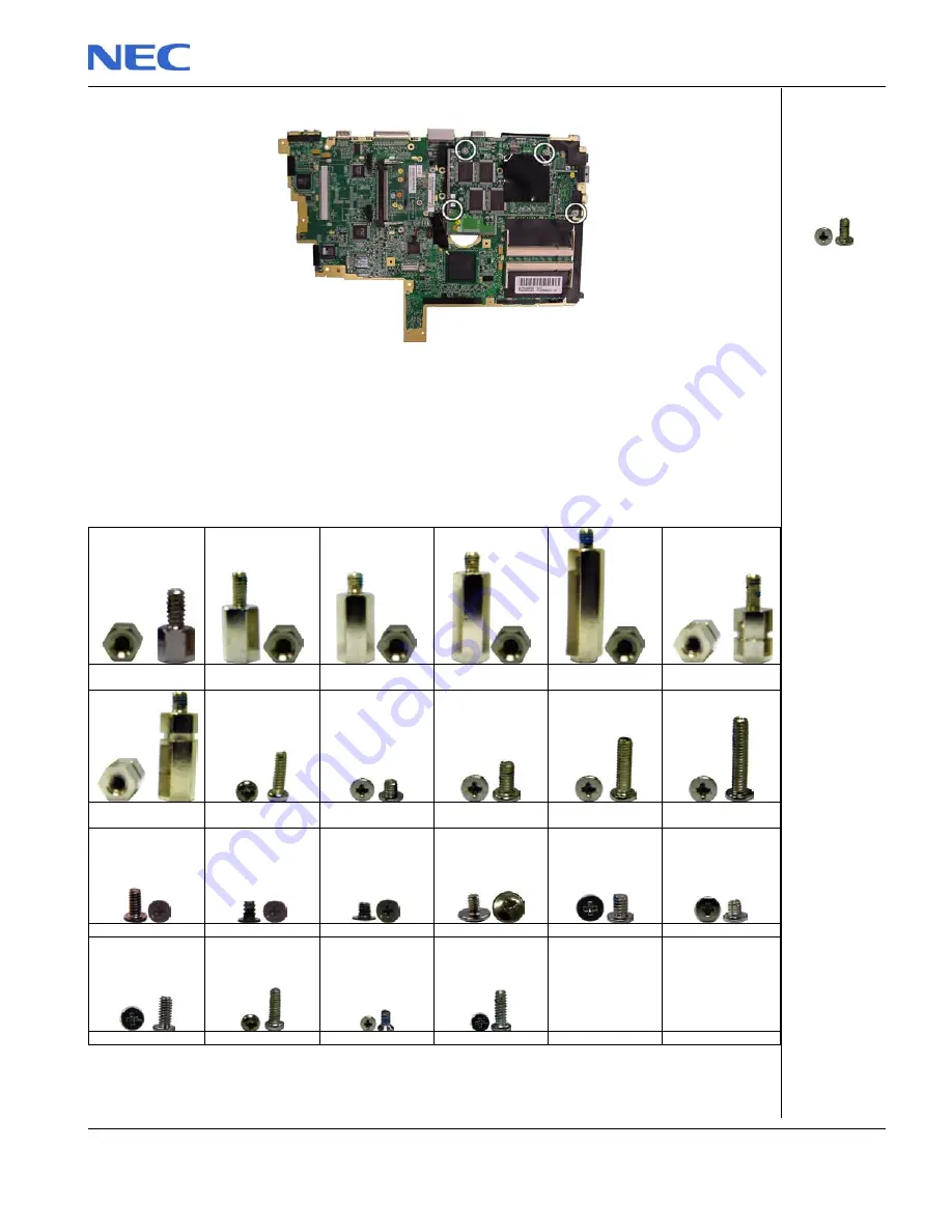
2.  Remove the screws retaining the video board to the main board. 


Fig. 53:  

Removing the video board 

3.  Carefully pull away the video board which is still attached to the main board through 

connectors and put it aside. 

Screws 


HEX Spacer 5 mm 

HEX Spacer 8 mm 

HEX Spacer 10 mm 

HEX Spacer 12 mm 

HEX Spacer 16 mm 

HEX Spacer 

w/groove 7 mm 


HEX Spacer 

w/groove 12 mm 

M2x10 mm 

M2.5x3 mm 

M2.5x5 mm 

M2.5x9 mm 

M2.5x12 mm 


M2x4 mm 

M2x3 mm 

M3x3 mm 

M2x3 mm 

M2x3 mm 

M2x2 


M2x5 mm 

M2x6 mm 

Cone 2.5x3 mm 

M1.5x6 mm 


(M2.5x5) 


Содержание Versa P700

Страница 1: ...NEC Versa P700 Disassembly Manual ...

Страница 2: ...Memory Module 7 Removing the Keyboard 8 Removing the LED Assy 9 Removing the LCD display 10 Disassembling the LCD display 12 Removing the Hard Disk Drive 15 Removing the Touchpad 17 Removing the Speaker Set 18 Removing the CPU 19 Removing the Heat Plate 20 Removing the CMOS Battery 20 Removing the Plastic Cover 21 Removing the Power Switch 22 Removing the Wireless LED Board 22 Removing the IDE Aud...

Страница 3: ...afety hazard Any indication of component replacement or printed wiring board modifications may void any warranty or exchange allowances Disassembly Instructions When disassembling the system unit follow these general rules Do not disassemble the system into parts that are smaller than those specified in the instructions Label all removed connectors Note where the connector goes and in what positio...

Страница 4: ...y surface Before you install or remove memory modules video memory disk drives circuit cards or other devices protect them from static electricity To do so make sure your computer s power switch is OFF Then unplug the computer s AC power cord Before picking up the device you un install you should wear an anti static wrist wrap available at electronic supply stores Be sure to connect the wrist wrap...

Страница 5: ...of the notebook 3 Turn the unit upside down 4 Unlock the battery and lift it out of its place as shown here Fig 1 Removing the battery Removing the VersaBay IV Perform the following steps to remove the VersaBay IV 5 Slide the latch as shown in the image below to unlock the VersaBay IV Fig 2 Removing the VersaBay IV 6 Carefully extract the VersaBay IV from its location ...

Страница 6: ...e MultyBay 2 Carefully extract the MultyBay from its location Removing the Wireless Mini PCI Card Perform the following steps to remove the Wireless Mini PCI Card 1 Unscrew one screw to open the cover assy 2 Carefully disconnect the two antenna wires connected to the wireless mini PCI card Fig 4 Removing the Mini PCI Antenna wires 3 Pull apart the retaining clips to release the mini PCI card M2 5x...

Страница 7: ...Mini PCI Card 1 Unscrew one screw to open the cover assy 2 Unscrew the two black screws Fig 6 Removing the modem screws 3 Disconnect the modem by pulling it away carefully Removing the Memory Module Perform the following steps to remove the memory module 1 Unscrew one screw to open the cover assy 2 Pull apart the retaining clips in order to release the memory module M2 5x3 M2x4 M2 5x3 ...

Страница 8: ...rewdriver between the function keys and the keyboard cover Fig 8 Removing the keyboard cover 2 Lever until the keyboard cover comes loose Then put the keyboard cover aside 3 Carefully lift the keyboard and put it face down on the front part of the notebook taking care not to rip off the keyboard cable 4 Locate the connector on the main board where the keyboard cable is attached ...

Страница 9: ...tract the antenna cable that passes to the hole in the LED assy and goes to the Wireless Mini PCI Card Note You will need to disconnect the antenna cable from the Wireless Mini PCI Card if you have not done so previously Refer to the section Removing the Wireless Mini PCI Card for instructions 2 Disconnect the flat cable from the LED assy by unlocking the retaining latch and carefully removing the...

Страница 10: ...remove the LED assy and put it aside Removing the LCD display To remove the LCD display first remove the keyboard cover see Removing the Keyboard disconnect the antenna from the Wireless Mini PCI Card see the section Removing the Wireless Mini PCI Card then perform the following steps 1 Close the LCD cover 2 Turn the notebook up side down 3 Remove the two screws shown in the picture that follows A...

Страница 11: ...xt picture Fig 14 Removing the back screws of the LCD 7 Now turn the notebook back in the normal position and open the cover 8 Remove the screws holding the LCD hinge shown below Fig 15 Removing the LCD hinge screws 9 Remove the screw holding the LCD flat cable connector onto the main board M2 5x9 M2 5x5 A M2 5x5 B M2 5x3 ...

Страница 12: ...to the section Removing the LCD Display for instructions on how to do that After removing LCD display do as follows 1 Remove the four rubber tabs and the two stickers that seal the retaining screws of the frame cover Fig 17 Removing LCD rubber tabs and screw seals 2 Remove the screws discovered by removing the rubber tabs and the stickers in the previous step 3 Unclip the LCD front cover from the ...

Страница 13: ...ps to break if the operation is not carefully performed 4 Remove the plastic hinge cover from the assembly carefully freeing it from the antenna cables and the flat cable Fig 19 Removing plastic hinge 5 Remove the screw that holds the LCD inverter board in position and the screw holding the cable on the frame then carefully lift the LCD inverter board from its location Fig 20 Removing LCD inverter...

Страница 14: ...the LCD assembly the screws shown in the next picture Fig 23 Removing antenna and hinge screws Note At the right side of the LCD assembly all four screws have all the same size namely M2x3 9 Carefully remove the LCD from the back cover 10 Remove the screws marked in the next picture to free the bare LCD panel from the hinges Fig 24 Removing hinges screws 11 Turn the LCD panel face down M2 5x5 A M2...

Страница 15: ... careful when removing the tape not to cause any damage to either cable or connector Removing the Hard Disk Drive Perform the following steps to remove the hard disk drive 1 Turn the notebook up side down 2 Remove the screws shown in the picture below Fig 26 Removing the hard disk drive cover screws 3 Turn the notebook back in the normal position 4 Remove the hard disk drive cover sliding out of i...

Страница 16: ...er 5 Slide the hard disk drive as shown in the next picture to disconnect it and carefully lift it out of the system Fig 28 Removing the hard disk drive 6 Finally remove the black screws shown next to free the hard disk drive from its brackets Fig 29 Removing the bracket screws M3x3 ...

Страница 17: ... 4 Carefully lift and tilt the touchpad assembly and lay it face down on the system Note Observe care when performing this operation The touchpad is still connected to the system via a small flat cable that might damage if you do not operate carefully 5 Disconnect the flat cable of the touchpad from the system as shown below Now you can remove the touchpad assembly from the system Fig 31 Disconnec...

Страница 18: ...ving the Speaker Set To remove the speaker set first remove the Hard disk drive cover see Removing the Hard Disk Drive remove the touchpad assembly see Removing the Touchpad then perform the next steps 1 Remove the one screw holding down the left speaker 2 Disconnect the speakers from the audio board refer to the picture below for the location of screw and connector mentioned Fig 34 Removing the s...

Страница 19: ...e left side of the heat sink and loosen the four other screws in the center of the heat sink Fig 35 Removing the heat sink 2 Remove the conducting tape connecting the heat sink with the heat plate 3 Carefully lift the heat sink and disconnect the two CPU fan connectors Fig 36 Removing the CPU fan connectors 4 Unlock the CPU with an appropriate screwdriver by turning CPU lock anti clockwise A M2x4 ...

Страница 20: ... remove the touchpad assembly see Removing the Touchpad then perform the following steps 1 Remove the seven screws marked in the next picture Fig 38 Removing the heat plate screws 2 Carefully lift out the front side of heat plate from the system slide the heat plate slightly towards the left side to free it from the plastic cover and put it aside Removing the CMOS Battery To remove the CMOS batter...

Страница 21: ... see Removing the LCD Display remove the heat sink see Removing the CPU remove the Hard disk drive cover see Removing the Hard Disk Drive remove the touchpad assembly see Removing the Touchpad remove the heat plate see Removing the Heat Plate then perform the next steps 1 Remove the screw on the bottom of the system at the VersaBay location see picture below Fig 40 Removing screw in VersaBay locat...

Страница 22: ...ing the LCD Display remove the heat sink see Removing the CPU remove the Hard disk drive cover see Removing the Hard Disk Drive remove the touchpad assembly see Removing the Touchpad remove the heat plate see Removing the Heat Plate remove the plastic cover see Removing the Plastic Cover then perform the next steps 1 Take the plastic cover that was removed in the section Removing the Plastic Cover...

Страница 23: ...e IDE Audio Board and Microphone To remove the IDE Audio board and microphone first remove the keyboard see Removing the Keyboard remove the LED assy see Removing the LED Assy remove the LCD assembly see Removing the LCD Display remove the heat sink see Removing the CPU remove the Hard disk drive see Removing the Hard Disk Drive remove the touchpad assembly see Removing the Touchpad remove the hea...

Страница 24: ...ee Removing the CPU remove the Hard disk drive see Removing the Hard Disk Drive remove the touchpad assembly see Removing the Touchpad remove the heat plate see Removing the Heat Plate remove the plastic cover see Removing the Plastic Cover remove the wireless LED board see Removing the Wireless LED Board remove the speaker set see Removing the Speaker Set remove the IDE Audio board see Removing t...

Страница 25: ... 48 Removing metal plate at VersaBay location 4 Remove the screws marked below that hold the rails for the Multibay Fig 49 Removing the MultiBay rails 5 Now you can remove the screw disconnect the lid switch and put it aside Fig 50 Removing the lid switch 6 Remove the screws at the back of the notebook as shown M2 5x5 A HEX 12 mm B M2x4 C M2x6 M1 5x6 ...

Страница 26: ...previously been removed they will also be still on the motherboard on the same side as the video board Please refer to Removing the Memory Module Removing the Wireless Mini PCI Card Removing the MDC Modem for instructions on the removal of such parts Removing the Video Board To remove the video board first remove the main board see Removing the Main Board then follow the next steps 1 Take the main...

Страница 27: ...eo board which is still attached to the main board through connectors and put it aside Screws HEX Spacer 5 mm HEX Spacer 8 mm HEX Spacer 10 mm HEX Spacer 12 mm HEX Spacer 16 mm HEX Spacer w groove 7 mm HEX Spacer w groove 12 mm M2x10 mm M2 5x3 mm M2 5x5 mm M2 5x9 mm M2 5x12 mm M2x4 mm M2x3 mm M3x3 mm M2x3 mm M2x3 mm M2x2 M2x5 mm M2x6 mm Cone 2 5x3 mm M1 5x6 mm M2 5x5 ...

Страница 28: ...NEC Versa P700 Disassembly Manual Page 28 ...

Страница 29: ...MAGES RESULTING FROM THE FURNISHING PERFORMANCE OR USE OF THIS MATERIAL Copyright 2003 NEC Computers International BV All rights reserved NEC is a trademark of NEC Computers International BV The names of actual companies and products mentioned herein may be trademarks and or registered trademarks of their respective owners The software described in this guide is furnished under a license agreement...

Отзывы: