background image

System Configuration and Setup   2-39

6. 

Firmly push against the card until the connection is secure. If internal SCSI
devices are being installed, the device cable(s) must be routed from the PCI
card to the file bays.  Feed one end of the cable through the left side of the
back of the unit and gently pull it toward to the back of the SCSI device.
Connect to the SCSI device and the card.

7. 

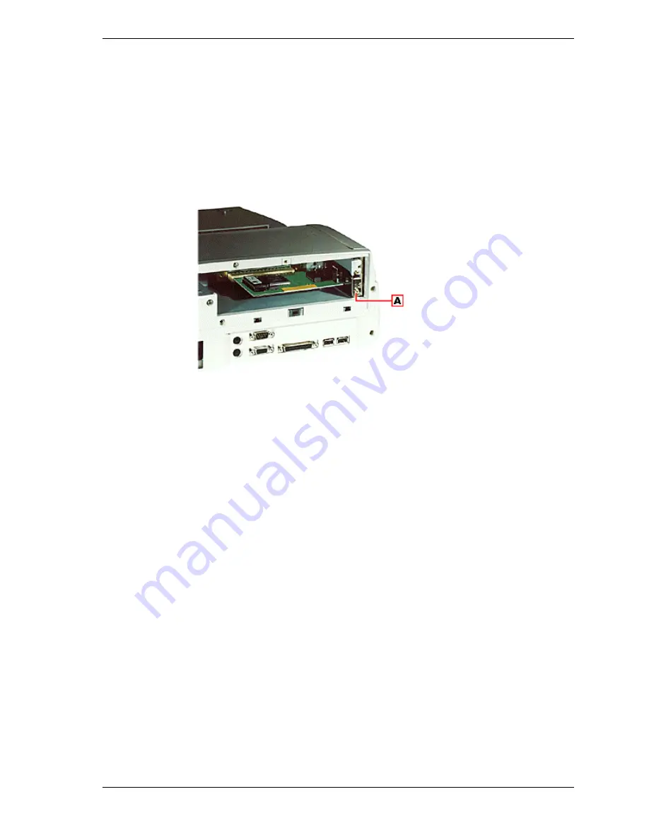
Replace the slot cover screw to secure the card.

Securing the card

A

- Slot cover screw

7. 

Attach device cables to the installed PCI card.

8. 

Replace the back cover of the NEC Versa Dock and secure it with the two
screws.

9. 

Reconnect the power cable.

Using PCI Cards

When using PCI cards, it is important that you check that the device is not
enabled in all configurations in the Device Manager. You can check this by
using the following procedure.

1. 

After installing the PCI card and drivers, click Start, Settings, and Control
Panel.

2. 

Double click System.

3. 

Click the Device Manager tab. Select the card type from the list, highlight
the PCI card, and click Properties.

4. 

Under the General tab, make sure the box “Exists in all hardware profiles” is
not checked. If it is checked, remove the check.

Содержание VERSA DOCK - SERVICE

Страница 1: ... of the Warranty Statement accompanying each product However actual performance of each such product is dependent upon factors such as system configuration customer data and operator control Since implementation by customers of each product may vary the suitability of specific product configurations and applications must be determined by the customer and is not warranted by NECCSD To allow for des...

Страница 2: ... to operate the docking station Section 3 Disassembly and Reassembly provides detailed instructions on how to disassemble and reassemble the docking station Section 4 System Board Layout and Board Connectors shows the system boards and the board connectors Section 5 Illustrated Parts Breakdown shows the Illustrated Parts Breakdown IPB and corresponding part numbers Section 6 Preventive Maintenance...

Страница 3: ...acknowledge DC direct current DIP dual in line package DLAB Divisor Latch Address bit DMA direct memory access DMAC DMA controller DOS disk operating system DRAM dynamic RAM ECC error checking and correction EDO extended data output EGA Enhanced Graphics Adapter EPROM erasable and programmable ROM EVGA Enhanced Video Graphics Array F Fahrenheit FAX facsimile transmission FCC Federal Communications...

Страница 4: ...t pixel picture element PLCC plastic leaded chip carrier PLL phase lock loop p p peak to peak PPI programmable peripheral interface PROM programmable ROM QFP quad flat pack RAM random access memory RAMDAC RAM digital to analog converter RAS row address strobe RGB red green blue RGBI red green blue intensity ROM read only memory rpm revolutions per minute R read RTC real time clock R W read write S...

Страница 5: ...2 9 Locking the NEC Versa 2 13 Undocking the NEC Versa 2 15 Emergency Undocking 2 17 Installing Options and Connecting Devices 2 18 Installing Devices in the File Bays 2 19 Installing Devices in the File Bays 2 19 Installing PCI Cards 2 32 Installing PC PCMCIA Cards 2 34 Connecting External Devices 2 35 3 Disassembly and Reassembly Required Tools and Equipment 3 2 Disassembly 3 2 Preparation for D...

Страница 6: ...shooting 7 2 Helpful Questions 7 4 8 Getting Services and Support Services and Support Contact Information 8 2 NEC NOW 8 3 NEC CSD Web Site 8 3 NEC CSD FTP Site 8 4 NEC CSD FaxFlash Service 8 4 Email Fax to Support Services 8 5 NEC CSD Bulletin Board 8 6 NEC CSD Support Services 8 7 NEC CSD Customer Assistance Center 8 8 Versa Laptop Fulfillment Hotline 8 8 9 Specifications Features 9 2 Input Outp...

Страница 7: ...1 Introducing the NEC Versa Dock n Carton Contents n NEC Versa Dock Features n The Right Environment ...

Страница 8: ...vironment Carton Contents Unpack and check the contents of the NEC Versa Dock carton Be sure you have the hardware components shown in the following figure and that they are in good condition If anything is damaged or missing contact your dealer immediately Carton Contents A NEC Versa Dock B CRT base C BIOS update diskette D Software Setup CD E IDE power cables F User documentation G AC power cabl...

Страница 9: ...ong Use connector type IEC320 In Europe the cable should be rated for 230 V 220 240 V 10A The plug is country specific Use an H05VV F or H05VVH2 F cable that is less than 15 feet 4 5 m long Use connector type EN60320 n NEC Versa Dock Keys NEC Versa Dock Features NEC Versa Dock features are found on all sides of the unit To become familiar with these features read each of the following sections Fro...

Страница 10: ... the left file bay with the added versatility that allows you to install the optional VersaBay III Adapter Kit With the VersaBay III Adapter kit installed you can use any of your VersaBay III options in the file bay n Power Button Allows you to power on and off the NEC Versa LX or SX notebook computer while docked on the NEC Versa Dock n Status LEDs LEDs on the front of the unit inform you of the ...

Страница 11: ...owered off Keylock Status Lights as follows Off No NEC Versa is docked Steady Amber The NEC Versa is docked but not locked on the NEC Versa Dock The key is in either the Normal position with the notebook turned off or in the Manual position with the notebook on or off Steady Yellow The NEC Versa is locked onto the NEC Versa Dock through software The key is in the Normal position and the NEC Versa ...

Страница 12: ...The installed battery is fully charged or no battery is installed n Docking Undocking Button Initiates the automatic sequence for docking or undocking your system if the keylock is in the normal position Left Side Features found on the left hand side of the NEC Versa Dock are shown in the following figure Features are described after the figure Left side features A PCI external access B Height lev...

Страница 13: ...orts Connects external audio devices including a microphone headphones or speakers You can also connect other audio devices to use as an output device or input source n MIDI Game Port Supports MIDI Game devices such as a joystick or MIDI keyboard ...

Страница 14: ... from being removed from the NEC Versa Dock You must use the key to unlock the unit before removing the NEC Versa Normal Default position Allows you to motorize dock or undock the NEC Versa Set the keylock to this position for normal use To prevent electrical damage manual undocking is not allowed when the keylock is in this state Manual Allows you to remove the NEC Versa by hand Use the unlocked ...

Страница 15: ...board Port Allows you to connect an external keyboard to the NEC Versa Dock n Kensington Lock Port Allows you to secure your NEC Versa Dock using an optional Kensington Lock n USB Ports Allows you to connect Universal Serial Bus devices to the NEC Versa Dock n Parallel Port Allows you to connect a parallel device to the NEC Versa Dock n Serial Port Allows you to connect a serial device to the NEC ...

Страница 16: ... the front back and sides of the unit n Choose an area away from extreme temperatures direct sunlight excessive dust vibration shock or moisture Operating Environment Use the NEC Versa Dock in a location that meets the following environmental conditions n Temperature 41 F to 95 F 5 C to 35 C n Humidity 20 to 80 non condensing Storage Environment Store the NEC Versa Dock in a location that meets th...

Страница 17: ...2 System Configuration and Setup n Setting Up Software n Docking and Undocking n Installing Options and Connecting Devices ...

Страница 18: ... Versa SX with Pentium II choose the BIOS Update for the NEC Versa SX Series with Pentium II n NEC Versa LX with Pentium I choose the BIOS Update for the NEC Versa LX Series with Pentium I n NEC Versa LX with Pentium II choose the BIOS Update for the NEC Versa LX Series with Pentium II Use only the BIOS update diskette included with the NEC Versa Dock and be sure to prepare the diskette before upg...

Страница 19: ...ocked please exit the BIOS Update Utility power down and undock your NEC Versa before running the utility Plug in your power cable before restarting the flash utility 1 Press Enter to continue The utility checks the currently installed BIOS version and the diskette s BIOS version The Main menu appears 1 Use the arrow keys to highlight the Display BIOS Version option on the Main menu Use this optio...

Страница 20: ...tup CD dialog box appears follow these steps to install the desired software 1 Insert the NEC Versa Dock Software Setup CD into the CD ROM reader If you have a combination of two CD ROM devices installed in the NEC Versa and the NEC Versa Dock be sure you have the NEC Versa Dock Software Setup CD in the CD ROM drive that was installed first and has the lowest assigned drive letter such as D or E 2...

Страница 21: ...plication click on the NEC Online Documentation tab 2 Click on the NEC Versa Dock User s Guide checkbox 2 Click OK to launch the Setup program The Setup program installs the online version of this user s guide 5 To access the user s guide double click on the NEC Versa Dock User s Guide icon that appears on the desktop Uninstalling the Online User s Guide To uninstall the online NEC Versa Dock User...

Страница 22: ...ninstall method Some of the files may be shared by other applications and deleting them may affect other programs 4 The Uninstall Wizard guides you through the rest of the uninstall process The NEC Versa Dock User s Guide and its desktop icon are removed from your system ...

Страница 23: ...ersa and NEC Versa Dock up and running Connect the AC power cable to the NEC Versa Dock and AC power before docking the computer The power cable that came with the NEC Versa Dock provides power to both the NEC Versa Dock and the NEC Versa when docked If you need to replace the NEC Versa Dock power cable make sure it meets the following specifications n In North America the cable should be rated fo...

Страница 24: ...e you to set the voltage selection switch to 115 volts In many European countries however the voltage setting switch should be set to 230 1 Position the NEC Versa Dock on a flat surface close to an AC outlet 1 Attach one end of the cable to the AC power port on the NEC Versa Dock 1 Attach the other end to a properly grounded wall outlet Connecting the power cable The NEC Versa Dock is now powered ...

Страница 25: ...Suspend mode leave it in full Operation mode for docking or you can choose to power off n If you have a non Plug and Play operating system such as Windows NT 4 0 turn off the system power before docking Make sure your system is in the appropriate mode for docking 2 If you are running the NEC Versa on AC power save any open files close open applications and disconnect the AC adapter cable from the ...

Страница 26: ...t cover 4 Verify that the power cord is plugged into the NEC Versa Dock See Connecting the Power Cable for details 5 Ensure that the keylock switch is in the Normal position Motorized docking is only enabled when the keylock switch is in the full upright position ...

Страница 27: ...h NEC Versa system power off This method works for all NEC Versa models that support docking n Warm Docking with NEC Versa power on the system in Suspend mode and NEC Versa Dock power on This procedure can be used with NEC Versa systems with Plug and Play operating systems such as Windows 95 n Hot Docking with NEC Versa power on and the system in full operation mode This procedure can be used with...

Страница 28: ...et to the correct height for system docking The NEC Versa Dock will not properly dock the NEC Versa if the height lever is set incorrectly which may result in system damage to either the NEC Versa Dock or the NEC Versa The Docking LED blinks amber if the height lever is set incorrectly n If you have an NEC Versa LX set the lever to I by sliding the lever to the front n If you have an NEC Versa SX ...

Страница 29: ...3 4 Close the LCD panel on the NEC Versa 5 Slide the NEC Versa onto the NEC Versa Dock Ensure that the three locking teeth on the NEC Versa Dock fit into the three locking slots on the bottom of the NEC Versa Locating the locking teeth ...

Страница 30: ...rsa Dock locking teeth Locating the locking slots A NEC Versa locking slots Once the notebook is properly seated on the docking teeth the docking connector and the expansion port are properly aligned Aligning the NEC Versa with the NEC Versa Dock ...

Страница 31: ... Docking Status LED blinks amber remove the NEC Versa using the Dock Undock button reseat it and retry docking 8 If using the NEC Versa without an external monitor open the LCD panel 10 If the system was cold docked press the Power button on the NEC Versa Dock to power on the NEC Versa 11 Verify that the Docking Status LED is steady green indicating the NEC Versa is properly docked on the NEC Vers...

Страница 32: ...or proper operation of the NEC Versa Dock Attempting to move the NEC Versa system with the key in this intermediate position could result in excessive noise from the NEC Versa Dock motor When using the keylock make sure to fully turn the key to the desired Normal or Manual position It may be necessary to apply additional pressure when turning the keylock to the Manual position Turning the keylock ...

Страница 33: ...System Configuration and Setup 2 17 ...

Страница 34: ...d but not locked on the NEC Versa Dock The key is in either the Normal position with the NEC Versa turned off or in the Manual position with the NEC Versa on or off n Steady Yellow The NEC Versa is locked onto the NEC Versa Dock through software The key is in the Normal position and the NEC Versa is on n Steady Green The NEC Versa is physically locked onto the NEC Versa Dock The key is in the Lock...

Страница 35: ...e NEC Versa mechanically ejects from the NEC Versa Dock Docking Undock Button A Dock Undock button To use Windows 95 software to undock the NEC Versa locate and select the Eject PC icon in the Windows 95 Start menu When you select this icon a Dock Change window appears 5 The NEC Versa Dock automatically ejects the NEC Versa Emergency Undocking To undock your NEC Versa Dock in the event of a power ...

Страница 36: ...rmediate position or stop between the Normal and Manual positions This is not a valid position for proper operation of the NEC Versa Dock Attempting to move the NEC Versa system with the key in this intermediate position could result in excessive noise from the NEC Versa Dock motor When using the keylock make sure to fully turn the key to the desired Normal or Manual position It may be necessary t...

Страница 37: ... external access to installed devices In the left front file bay you can install any optional 5 25 inch IDE device and with a 3 5 inch Universal Installation Kit you can install any 3 5 inch IDE device In the right front file bay you can install any optional IDE device or the optional VersaBay III Adapter Kit With this Adapter Kit you can change this file bay into a VersaBay III slot that lets you...

Страница 38: ...erboard n Replacing the NEC Versa Dock cable cover docking tray and front panel Use the instructions in the sections that follow to install an IDE device in a file bay and to install the optional VersaBay III Adapter Kit Installing Devices in the File Bays The NEC Versa Dock has two 5 25 inch half height bays for installing optional devices The bay located on the right front of the NEC Versa Dock ...

Страница 39: ...and undock the NEC Versa if it is docked 1 Disconnect any external cables that might be attached on an installed PCI board such as a network board 3 Turn the keylock switch to the Manual position to disengage the motor mechanism Keylock switch in the Manual position 4 Remove the front part of the docking tray First locate and remove the rubber pads securing the three screws then loosen and remove ...

Страница 40: ...place for use when replacing the front panel Removing the front panel A Front panel tabs 4 B Front panel screws 2 6 Slide the rear part of the docking tray towards the front of the NEC Versa Dock until it stops 7 Remove the cable cover by locating and removing the two top screws Put the screws in a safe place for use when replacing the cable cover Locating the cable cover screws A Cable cover scre...

Страница 41: ... for details Disconnecting the Cables from the Motherboard Disconnect the cables from the motherboard as follows 1 Before handling any internal components discharge static electricity from yourself and your clothing by touching a nearby metal surface 2 See the appropriate figure for the bay that you are using to disconnect cables from the motherboard The following figure shows cable locations in t...

Страница 42: ...dio cable from behind the left hand bay The NEC Versa Dock comes with only one audio cable You are now ready to attach the cables to the appropriate ports on the back of the device See the instructions in Connecting IDE Device Cables for details If you are installing an optional VersaBay III device see the instructions in Connecting VersaBay III Adapter Kit Cables for details Connecting IDE Device...

Страница 43: ...System Configuration and Setup 2 27 2 Locate the power cable and IDE signal cable port and if necessary the audio cable port on the back of the IDE device ...

Страница 44: ...y the audio cable to the ports on the back of the IDE device The IDE cable must be installed with the red stripe to the left side of the device 4 Ensure that the IDE connector pin is oriented correctly on the IDE signal cable If the power cable for the device you are installing uses a small connector use one of the cables provided in the accessory kit You are now ready to install the IDE device in...

Страница 45: ...e optional VersaBay III Adapter Kit You are now ready to install the optional VersaBay III Adapter Kit into the file bay See the instructions in File Bay Installation for details File Bay Installation Install an IDE device or the optional VersaBay III Adapter Kit in the file bay as follows 1 Before handling any internal components discharge static electricity from yourself and your clothing by tou...

Страница 46: ...curing the device bracket A Device bracket screws 2 As an added security feature the keylock switch must be in the Manual position before the file bay brackets can be removed If the keylock switch is in the Locked position the file bay bracket will not slide forward This prevents device removal while the keylock switch is in the Locked position 6 Verify that the keylock switch is in the Manual pos...

Страница 47: ... can short circuit and burn out the device Be sure to install 3 5 inch IDE devices in the file bays using a 3 5 inch Universal Installation Kit 9 Align the screw holes on the side of the device with the screw holes on the bracket Attach the device to the bracket using the four screws that came with the IDE device Attaching the device to the bracket A Device bracket screws 4 10 Slide the device and...

Страница 48: ...d Reconnecting the Cables to the Motherboard Reconnect the cables to the motherboard as follows 1 Before handling any internal components discharge static electricity from yourself and your clothing by touching a nearby metal surface 2 Locate the power cable slot IDE signal cable slot and the audio cable slot if necessary found directly behind the IDE device installed If you are installing the opt...

Страница 49: ...e 3 Reconnect the appropriate power cable and the IDE cable to the motherboard Also connect the audio cable or VersaBay III cable if necessary to the motherboard You are now ready to replace the NEC Versa Dock cable cover See the instructions in Replacing Covers Panels and Trays for details Replacing Covers Panels and Trays Replace the NEC Versa Dock cable cover front panel and docking tray as fol...

Страница 50: ...nd Setup 3 Replace the two screws on the top of the cable cover Replacing the cable cover screws A Cable cover screws 2 4 Slide the rear part of the docking tray towards the back of the NEC Versa Dock until it is seated properly ...

Страница 51: ...System Configuration and Setup 2 35 Make sure the docking connector is aligned with the hole in the docking tray as you slide the docking tray into place ...

Страница 52: ...ay cover s on the front panel by squeezing the two inside tabs together and gently pushing the bay cover out of the front panel NEC Versa Dock file bay covers A Bay cover tabs 2 6 Replace the front panel on the NEC Versa Dock by aligning the four tabs at the top then replacing the two bottom screws Replacing the front panel A Front panel tabs 4 B Front panel screws 2 ...

Страница 53: ...ock Only the top slot supports a full size card The optional NEC 3Com Fast EtherLink LX provides a networking solution for the NEC Versa Dock for systems running Windows 95 and Windows NT 4 0 This PCI card supports Wake on LAN technology which allows you to manage your networked systems remotely For installation and configuration information see the documentation that came with the NEC 3Com Fast E...

Страница 54: ... cover screws 2 4 Locate and remove the slot cover screw If you are installing a full size card remove the top PCI slot cover screw and the slot cover Removing the slot cover screw A Wake On LAN connector B Slot cover screws 5 Align the PCI card with the slot connector Inserting the card ...

Страница 55: ...evice cables to the installed PCI card 8 Replace the back cover of the NEC Versa Dock and secure it with the two screws 9 Reconnect the power cable Using PCI Cards When using PCI cards it is important that you check that the device is not enabled in all configurations in the Device Manager You can check this by using the following procedure 1 After installing the PCI card and drivers click Start S...

Страница 56: ...g external devices to the NEC Versa Dock Serial Device The NEC Versa Dock is equipped with an industry standard 9 pin RS 232C serial port Use this port to install a serial device such as a printer or an external modem When you connect a printer be sure to install the appropriate printer driver through the Windows Control Panel Follow these steps to connect a serial device to your NEC Versa Dock 1 ...

Страница 57: ... s guide for instructions 7 Turn on the power to the NEC Versa Dock External Keyboard and Mouse You can connect a full size PS 2 style keyboard and or PS 2 style mouse to your NEC Versa Dock You can continue to use the system keyboard or VersaGlide while an external keyboard or mouse is connected Follow these steps to connect an external keyboard or mouse to your system 1 For non Plug and Play ope...

Страница 58: ... Dock Connecting an external keyboard and mouse 3 For non Plug and Play operating systems such as Windows NT 4 0 power on the system The system immediately recognizes the keyboard or mouse After you connect an external keyboard you can use both the built in keyboard and external keyboard simultaneously Only the numeric keypad on the external keyboard works in this case External Monitor The NEC Ver...

Страница 59: ...or the system does not recognize the monitor type 2 Position the monitor as follows n To use the monitor without the monitor stand simply place the monitor on a flat surface next to the NEC Versa Dock n To use the monitor stand Close the LCD panel on the NEC Versa Lower the monitor stand onto the NEC Versa Dock Carefully center the external monitor on the monitor base Lowering the monitor base int...

Страница 60: ...tor 8 Power on the NEC Versa Press Fn F3 to toggle between the LCD CRT simultaneous CRT LCD display and TV Out on systems that support TV Out Parallel Devices To install a parallel device such as a printer you need a cable with a male 25 pin connector for the system and for most parallel printers a Centronics compatible 36 pin connector When you connect a printer be sure to install the appropriate...

Страница 61: ...gn and connect the 25 pin parallel cable connector to the parallel port on the NEC Versa Dock Secure the cable with the screws provided 3 Align and connect the other end of the cable to the parallel port on the device Lock the connector clips ...

Страница 62: ...vices The NEC Versa Dock lets you take advantage of the latest USB technology available to Windows 95 users Plug USB devices into your Windows 95 system as follows The USB hub on both the NEC Versa and the NEC Versa Dock are active at the same time You can connect USB devices to all three ports to further increase system connectivity Any external USB hubs you wish to connect to the NEC Versa Dock ...

Страница 63: ...k or MIDI device to your NEC Versa Dock Connect a joystick or MIDI device as follows 1 Check that both the NEC Versa and the device power are off 2 Locate the MIDI Game port on the side of the NEC Versa Dock 3 Plug in the joystick or MIDI device and power on the MIDI device and NEC Versa Dock Connecting a MIDI Game device ...

Страница 64: ...ophone line out and line in devices headphones or optional external speakers to the audio ports as follows 1 Power off the NEC Versa Dock and the NEC Versa 2 Locate the audio port that you want to use If the audio device you intend to use uses AC power the line out port is recommended If the audio device is unpowered the headphone jack is recommended 3 Plug the jack into the port on the side of th...

Страница 65: ...ntrollers Icon then double click the Maestro Wave WaveTable Synthesis Devices icon 4 Click on the Dock Settings tab Dock Settings Dialog Box 5 Select the Output Audio To Docking Station Speakers This resets the default speakers to the NEC Versa Dock optional external speakers When you undock the system your NEC Versa speakers will be functional When you dock again the external speakers will be fun...

Страница 66: ...g external speakers or an external microphone and experience sound distortion or feedback lower the volume Having the microphone and speakers too close to each other can also cause feedback Moving the external audio options away from each other may help ...

Страница 67: ...3 Disassembly and Reassembly n Required Tools and Equipment n Disassembly n Reassembly ...

Страница 68: ...be shown in the illustration The illustration and callouts are accurate for the described disassembly step The Illustrated Parts Breakdown and parts lists for the system unit are shown in Section 5 For complete disassembly of the Versa Dock follow the disassembly order listed below To reassemble follow the table in reverse order NEC Versa Dock Disassembly Sequence Level of Disassembly Components A...

Страница 69: ...l options and remove the notebook Removing Trays Panels and Covers To remove the docking tray front panel and cable cover Do so as follows 1 Undock the NEC Versa if it is docked unplug the NEC Versa Dock and disconnect any peripheral devices that are attached 2 Disconnect any external cables that might be attached on an installed PCI board such as a network board 3 Turn the keylock switch to the M...

Страница 70: ... Lift the docking tray up and off the NEC Versa Dock Removing the docking tray 5 Remove the front panel from the NEC Versa Dock by removing the two screws at the bottom freeing the four tabs from the top of the panel Removing the front panel A Front panel tabs 4 B Front panel screws 2 6 Slide the rear part of the docking tray towards the front of the NEC Versa Dock until it stops ...

Страница 71: ...he two top screws Put the screws in a safe place for use when replacing the cable cover Locating the cable cover screws A Cable cover screws 2 8 Lift the cable cover up and off the NEC Versa Dock Removing the cable cover You are now ready to disconnect the cables from the motherboard ...

Страница 72: ...electricity from yourself and your clothing by touching a nearby metal surface 2 See the appropriate figure for the bay that you are using to disconnect cables from the motherboard The following figure shows cable locations in the NEC Versa Dock Left hand bay cables A Power cable port B IDE signal port C Audio cable port D Audio cable E IDE signal cable F Power cable Right hand bay cables ...

Страница 73: ... device bracket A Device bracket screws 2 As an added security feature the keylock switch must be in the Manual position before the file bay brackets can be removed If the keylock switch is in the Locked position the file bay bracket will not slide forward This prevents device removal while the keylock switch is in the Locked position 2 Verify that the keylock switch is in the Manual position The ...

Страница 74: ...3 8 Disassembly and Reassembly Removing the bracket ...

Страница 75: ...ck cover by locating and removing the two screws A Locating and Removing the Back Cover Screws A Back cover screws 2 2 Remove the back plate by locating and removing the six screws n four screws B n two screws C Rear of Versa Dock 3 Remove four top cover screws A on the front of the top cover ...

Страница 76: ... the top cover notches and separate the side covers from the top cover tilt outward and lift from the notches on the base of the Versa Dock 6 Slide the top cover forward then tilt the top cover forward and past the docking pins when clear of the docking pins lift and remove Docking Connector Board PCI Housing and Power Supply Remove the docking connector board PCI card and expansion bay assembly a...

Страница 77: ...Disassembly and Reassembly 3 11 2 Remove two screws on the right side opposite the two just removed from the left side ...

Страница 78: ...he docking connector board sub assembly and PCI slot sub assembly Docking connector board screws 4 Remove four screws A The screws B C do not need to be removed to remove the docking connector sub assembly and PCI slot sub assembly Rear screws 5 Lift the sub assembly from the main unit ...

Страница 79: ...tor board by removing four screws B Screws for the PCI connector board and docking connector board Power Supply Remove the power supply by removing four screws two C on the back of the unit and two on the interior which secure the two right angled feet of the power supply It is necessary to disconnect any cables that still may be connected to the main board from the power supply Power Supply screw...

Страница 80: ...or Assembly Remove the docking tray assembly and motor assembly by removing eight screws A four from the left and four from the right as shown below Remove the motor assembly by removing two screws B as shown in the illustration Left side screws Right side screws ...

Страница 81: ...ews from the exterior of the unit three screws B from the left side Left side and six screws B from the rear Rear view 3 Continue the main board removal by completing the following n Remove six screws from the main board and n two screws from the cover plate n release the battery from the cover plate n remove the cover plate n Lift the main board from the unit 4 Remove eight stand offs to remove t...

Страница 82: ...ove the remaining items attached to the bottom assembly by removing the appropriate screws Reassembly Reassembly is the reverse of the disassembly process Use care to insure that all cables and screws are returned to their proper positions ...

Страница 83: ...4 System Board Layout n Main Board n LED Board n PCI Expansion Board ...

Страница 84: ...4 2 System Board Layout Main Board LED Board ...

Страница 85: ...System Board Layout 4 3 PCI Expansion Board ...

Страница 86: ...5 Illustrated Parts Breakdown n NEC Versa Dock Illustrated Parts Breakdown n Parts List ...

Страница 87: ...5 2 Illustrated Parts Breakdown NEC Versa Dock Illustrated Parts Breakdown ...

Страница 88: ...Illustrated Parts Breakdown 5 3 ...

Страница 89: ... 14 Front Mask Assy 136 243405 001 A 15 LED Badge 136 640256 A 16 Dummy Mask 136 640236 001 A 17 Dummy Mask 136 640236 001 A 18 5 File Plate 136 638803 A 19 5 File Plate R Assy 136 243725 001 A 20 5 File Plate L Assy 136 243412 001 A 21 Tilt Up Cap 136 640250 001 A 22 Side Cover L 136 640243 001 A 23 Ground Plate Included with item 43 24 Rear Panel 136 640234 001 A 25 PCI Slot Cover Assy 136 24366...

Страница 90: ...th item 14 NS Front Rubber Included with item 14 NS FG Strap FGM 100 M3 136 643513 A NS Core TFC 25 15 12 808 090339 001 A NS 5 File Plate Insulator 136 643289 A NS Micro SW Cable Insulator 136 642691 A NS CRT Table 136 243406 001A NS Sensor Pkg Insulator 136 641060 A NS Base Plate Assy 136 243722 001 A NS Table Bush 136 642034 001 A NS Sensor Cable Assy 808 743543 001 A NS Not shown key numbers s...

Страница 91: ...6 Preventive Maintenance n Precautions n Battery Charging n Routine Care n Cleaning the Versa Dock Interior n Protecting the Disk Drives ...

Страница 92: ...r knocking it over can cause serious damage n Keep the NEC Versa Dock away from machinery that generates strong electric or magnetic fields n Do not place heavy objects on the NEC Versa Dock Make sure the CRT base is in position before placing an external monitor on it The CRT base is designed to support an external monitor weighing no more than 55 pounds 25 kg Do not place other heavy objects on ...

Страница 93: ...magazines which might block the air vents and prevent proper air circulation Keep food and liquids away from the NEC Versa Dock and NEC Versa Preventive maintenance is limited to cleaning the plastic case the keyboard the display screen and the diskette drive heads as required Cleaning the Versa Dock Interior When servicing the inside of the notebook remove dust and other foreign particles from in...

Страница 94: ...ck for possible virus infected areas on the hard disk n Use the preinstalled ScanDisk program to correct any errors found in the directory and File Allocation Table FAT This also frees up space from any unused sectors n Never turn the computer off when the hard disk is being accessed n Never move or raise the computer while the hard disk is being accessed Be especially careful not to jar the hard ...

Страница 95: ...7 Troubleshooting n Quick Troubleshooting n Helpful Questions ...

Страница 96: ...k the VGA controller chip on the I O board for any loose soldering Replace the CPU board System halts during boot sequence Check condition of selected boot device diskette hard disk or CD ROM for bad boot track or incorrect OS files Try booting from a new bootable diskette and recopy or repartition hard disk Check for any BIOS error messages on the display screen I O processing malfunctions Check ...

Страница 97: ...y Clean VersaGlide surface Check the keyboard controller chip for any cold or loose soldering Replace the CPU board Serial device does not work Check if device driver is installed properly Check if serial device is connected properly Check the device drive installation for any IRQ or I O address conflict Replace serial device Check the I O controller chip on the main board for any cold or loose so...

Страница 98: ... and the Power LED activated n Is the LCD display switched to an external monitor n Are all cables and devices connected properly and securely n Are all needed device drivers installed properly n Have you checked the AUTOEXEC BAT and CONFIG SYS files for errors n Is the Standby Mode activated Press any key or press the Power switch to power on the system n Is the docking height lever in the correc...

Страница 99: ...rt Contact Information n NEC NOW n NEC CSD Web Site n NEC CSD FTP Site n NEC CSD FaxFlash Service n Email Fax to Support Services n NEC CSD Bulletin Board n NEC CSD Support Services n NEC CSD Customer Assistance Center n Versa Laptop Fulfillment Hotline ...

Страница 100: ...t Services U S and Canada customers only 800 632 4525 NEC CSD Customer Assistance Center 888 632 9128 Versa Laptop Fulfillment Hotline 800 842 6446 Note If you purchased your computer outside of the U S or Canada please contact the local NEC office or their dealers for support and service See the booklet Getting Service and Support in Asia Australia and Europe to find out how to contact the local ...

Страница 101: ... NEC CSD Web Site If you have a modem or a network board you can access the NEC CSD Web site You can do this through a commercial online service or through your Internet account The NEC CSD Web site contains general information about NEC CSD and its products an online store press releases reviews and service and support information Look in the Service and Support area for the following n technical...

Страница 102: ...achine you can obtain information from FaxFlash 24 hours a day 7 days a week Simply call the FaxFlash number on your touch tone telephone and order the information you want by following the voice prompts FaxFlash automatically faxes the information to you If you are new to FaxFlash first order one of the following catalogs Each catalog lists the available documents and their document numbers Curre...

Страница 103: ... The information you request will be automatically sent to your fax machine Please wait for the ordered document to arrive at your fax machine before calling to order more documents If FaxFlash attempts to send the second order before the first order is completed the order may be canceled After three tries FaxFlash assumes that your line is busy and terminates any further processing of the order E...

Страница 104: ...rive Log onto the BBS as follows 1 From the Windows desktop click the Start button 2 Point to Programs Point to Accessories and then click HyperTerminal 3 Double click the Hypertrm exe icon The HyperTerminal program appears 4 Follow the instructions on the screen to set up your modem Click the HyperTerminal help button for information about dialing the phone number If you need to check communicati...

Страница 105: ...k that you do not have information on the diskette that you need After you complete downloading your file log off the BBS as follows 1 Press Enter to continue 2 Press G command for Goodbye Hangup 3 Press Enter NEC CSD Support Services NEC CSD also offers direct technical support through Support Services NEC CSD Support Services is for U S and Canadian customers only international customers should ...

Страница 106: ...SD Customer Assistance Center NEC CSD offers Customer Service for extended warranty and contract information spare parts ordering warranty claims repair services and service authorizations Direct assistance is available Monday through Friday from 8 30a m to 8 00p m EST Call the NEC CSD Customer Assistance Center toll free at 1 888 632 9128 U S and Canada only Versa Laptop Fulfillment Hotline 800 8...

Страница 107: ...9 Specifications n Features n Input Output Facilities n Expansion Capabilities n Indicator LEDs n Power Supply n Power Cables n Dimensions n Environmental Requirements ...

Страница 108: ...port VersaBay III devices n Monitor stand that allows access to external PCI card connectors and NEC Versa PC card slots n Port replication of most NEC Versa I O ports Input Output Facilities n Docking connector 240 pin connector n Keyboard PS 2 style 6 pin connector n Mouse PS 2 style 6 pin connector n Two Universal Serial Bus USB 4 pin connector n Parallel port 25 pin D sub connector n External ...

Страница 109: ...t supports a half size card only Indicator LEDs n Docking Undocking LED n Key Lock Status LED n IDE Drive Access LED n Diskette Drive Access LED n Battery Charge LED Power Supply n Input Range 90 135 180 265 VAC switch select Frequency 50 60 Hz Input current 6 5A 115 VAC 3 5A 230 VAC n Output Maximum power 200 watt W Hold up time 7 ms at full load 115 VAC Over current protection 5V 50A 12V 25A Ove...

Страница 110: ...ntry specific Cable H05VV F or H05VVH2 F less than 15 ft 4 5 m in length Connector EN60320 Dimensions n Height 5 2 in 132 mm n Width 14 98 in 380 6 mm n Depth 16 93 in 430 mm n Weight 25 lb Environmental Requirements n Operating Environment Temperature 41 F to 95 F 5 C to 35 C Humidity 20 to 80 non condensing n Storage Environment Temperature 4 F to 140 F 20 C to 60 C Humidity 5 to 95 non condensi...

Страница 111: ...lection of primitive computer routines usually burnt into ROM that controls the real time clock keyboard disk drives video display and other peripheral devices bit Binary digit The smallest unit of computer data bits per second bps A unit of transmission board Printed circuit board Board onto which computer components are soldered and thin wires are printed to connect the components boot To start ...

Страница 112: ...pixels See also LCD cursor A movable image on the display screen that indicates where the next entered data appears D diskette A thin flexible platter coated with a magnetic material for storing information diskette drive A magnetic drive that writes on and retrieves data from a diskette DSTN Double Scan Super Twisted Nematic A type of technology used in some Versa LCD screen displays E enhanced V...

Страница 113: ...igent Drive Electronics A hard disk drive type that has controller electronics built into the drive and delivers high throughput interface A connection that enables two devices to communicate interrupt A special control signal from an I O device that diverts the attention of the microprocessor from the program to a special address K kilobyte KB 1024 bytes L LAN Local Area Network LCD Liquid Crysta...

Страница 114: ...r DEModulator A device that links computers over a telephone line N nonvolatile memory Storage media that retains its data when system power is turned off Nonvolatile memory in the Versa is a complementary metal oxide semiconductor CMOS chip which is backed up by an internal battery The backup battery preserves the clock calendar data and system configuration parameters stored in CMOS See volatile...

Страница 115: ...e fax modems LAN storage cards and wireless communications devices Also known as PC card peripheral Input or output device not under direct computer control A printer is a peripheral device pixels Picture elements Tiny dots that make up a screen image port Provides the means for an interface between the microprocessor and external devices A cable connector is usually plugged into the port to attac...

Страница 116: ...aterial and converts it to a computer screen image serial interface An interface that communicates information one bit at a time serial printer A printer with a serial interface software Programs that run on a computer such as operating systems word processors and spreadsheets super video graphics array SVGA A color bit mapped graphics display standard that provides a resolution of 1024x 768 with ...

Страница 117: ...ower is turned off Standard memory and memory that you add to the Versa are volatile memory See nonvolatile memory W warm boot Process of resetting the computer without turning off the power through keyboard input pressing Ctrl Alt and Del keys simultaneously or the reset button The system returns to an initial or arbitrarily selected condition write To record or store information to a storage dev...

Страница 118: ...Device Manager checking PCI card configuration 2 35 Disassembly guidelines 3 2 Docking 2 9 cold 2 9 hot 2 9 warm 2 9 Docking station features 1 3 front 1 3 top 1 3 Docking status LED 1 4 E Emergency undocking 2 17 Environmental requirements 1 9 External devices connecting 2 19 External monitor 2 38 External speakers 2 44 F Features 1 3 File bay installation 2 26 G Game port 2 42 H Hardware setup 2...

Страница 119: ... using 2 35 PCI connectors 2 33 Power cable connection 2 6 Power cable requirements 1 3 Precautions 6 2 Preparing to dock 2 7 Printers 2 40 Q Quick troubleshooting 7 2 R Routine care 6 3 S Serial devices 2 36 Services and Support contact information 8 2 Servicing a hard disk 6 4 Servicing the system required tools 3 2 Setting up the hardware 2 6 Speakers 2 44 Specifications 9 2 Storage environment...

Страница 120: ...TENTION Il y a danger d explosion s il y a replacement incorrect de la batterie Remplacer uniquement avec une batterie du même type ou d un type recommandé par le constructeur Mettre au rébut les batteries usagées conformément aux instructions du fabricant BATTERY DISPOSAL The main battery is made of Lithium Ion Li Ion and the CMOS clock battery is made of Lithium Your bridge battery not the main ...

Страница 121: ...e receiving antenna Increase the separation between the equipment and receiver Connect the equipment to an outlet on a circuit different from the one to which the receiver is connected To meet FCC standards shielded cables and power cords are required to connect this device to a personal computer or other Class B certified device Canadian Department of Communications Compliance Statement This equi...

Отзывы: