background image

Setup and Operation     2-7


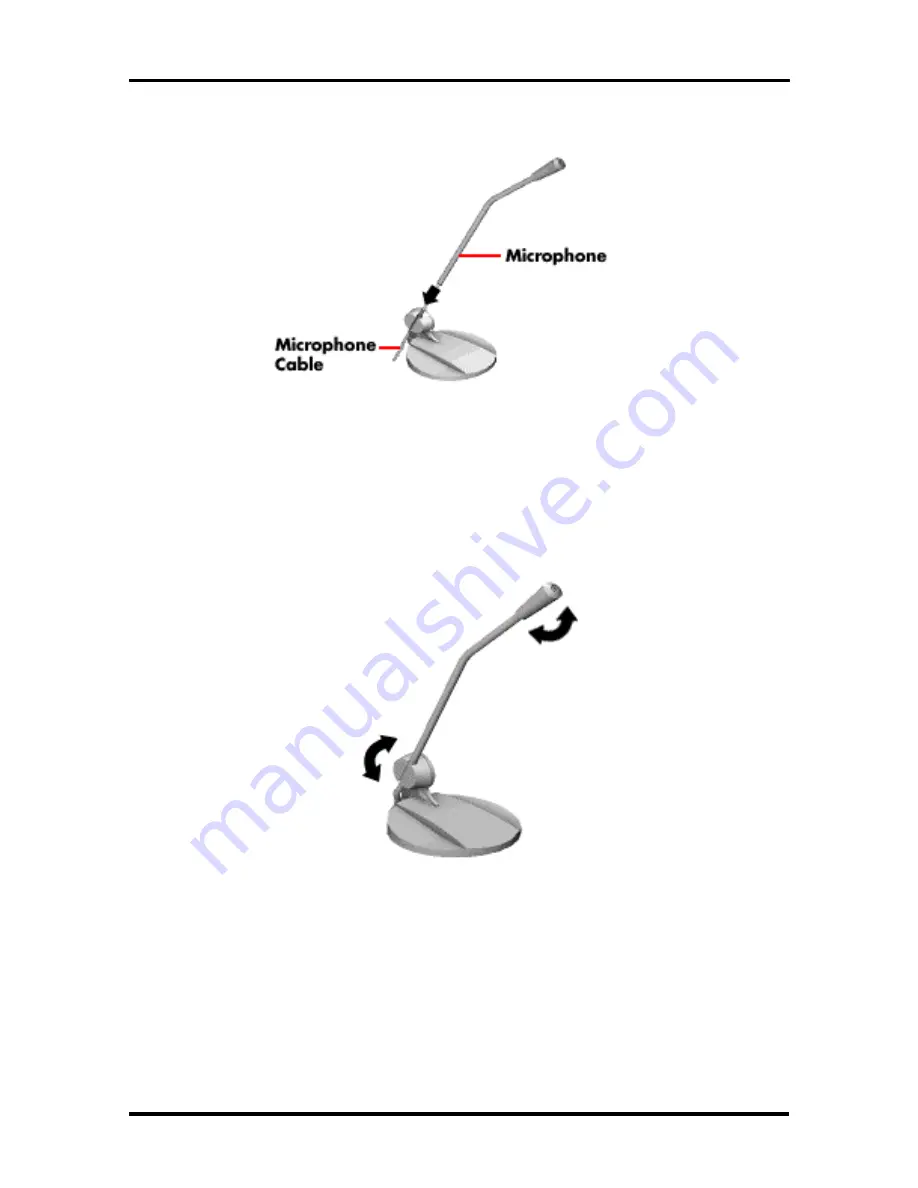
Figure Section 2-8   Inserting the microphone into the holder

n


Adjust your microphone by pivoting it up and down and side to side (see
Figure Section 2-9).

 Figure Section 2-9   Assembling the Microphone Holder

n


Plug the microphone into the microphone in jack at the rear of the system (see
Figure Section 2-10).


Содержание POWERMATE P - SERVICE 1996

Страница 1: ...NEC PowerMate P Service and Reference Manual Printed in U S A 4 96 819 181410 000 Rev 00...

Страница 2: ...h the terms of the Warranty Statement accompanying each product However actual performance of each such product is dependent upon factors such as system configuration customer data and operator contro...

Страница 3: ...Video Controller 1 11 Graphics Accelerator 1 12 Video Memory 1 12 ISA Bus 1 13 PCI Local Bus 1 13 PCI IDE Ports 1 14 Parallel Interface 1 14 Serial Interface 1 15 Infrared Interface 1 16 Power Supply...

Страница 4: ...Menu Bar 2 13 Legend Bar 2 14 Field Help Window 2 15 General Help Window 2 15 Main Menu Options 2 15 IDE Adapters 2 16 Memory Cache 2 19 Memory Shadow 2 19 Boot Options 2 19 Numlock 2 20 Advanced Menu...

Страница 5: ...emoval 3 15 Processor Installation 3 16 Data Storage Devices 3 17 Device Slots 3 17 Device Preparation 3 18 Device Cables 3 18 Diskette Drive Signal Cable 3 20 IDE Signal Cables 3 21 System Power Cabl...

Страница 6: ...e Removal 5 7 3 1 2 Inch Drive Bracket Removal 5 9 Card Guide Fan Bracket Removal 5 9 Speaker Assembly Removal 5 10 3 1 2 inch Diskette Drive Removal 5 11 5 1 4 Inch Device Removal 5 12 Rear Internal...

Страница 7: ...Appendix C Hard Disk Drive Specifications and Jumper Settings Hard Disk Drive Specifications C 1 1 6 GB Hard Disk Drive Jumper Settings C 2 2 0 GB Hard Disk Drive Jumper Settings C 3 J5 Master Slave...

Страница 8: ...ptional Diskette Drive Signal Cable 3 20 3 14 Optional IDE Cable Connectors 3 21 3 15 Power Cable Connectors 3 22 3 16 Connecting IDE Device Cables 3 23 3 17 Connecting 1 2 MB Diskette Drive Cables 3...

Страница 9: ...ng the Device Rails 5 14 5 17 Removing the Drive Bracket Screws 5 15 5 18 Securing the Drive to the Bracket 5 15 5 19 Power Supply Screws 5 16 5 20 PCI ISA Backboard 5 17 5 21 System Board Removal 5 1...

Страница 10: ...4 6 4 5 Diagnostic Beep Codes 4 10 5 1 PowerMate P Series System Unit Disassembly Sequence 5 1 5 2 PowerMate P Series Field Replaceable Parts List 5 18 5 3 PowerMate P Series Video Upgrade Options 5...

Страница 11: ...ISA Expansion Slot Pin Assignments A 14 A 15 CD Audio In Connector A 16 C 1 Hard Disk Drive Specifications C 1 C 2 1 6 GB Hard Disk Jumper Settings C 2 C 3 2 GB Hard Disk Master Slave Select Jumper S...

Страница 12: ...and hard disk storage devices system and video memory and processor updates Section 4 Maintenance and Troubleshooting includes recommended maintenance information and lists possible problems and solu...

Страница 13: ...ivisor Latch Address bit DMA direct memory access DMAC DMA controller DOS disk operating system DRAM dynamic RAM ECC error checking and correction EGA Enhanced Graphics Adapter EPROM erasable and prog...

Страница 14: ...phase lock loop p p peak to peak PPI programmable peripheral interface PROM programmable ROM QFP quad flat pack RAM random access memory RAMDAC RAM digital to analog converter RAS row address strobe R...

Страница 15: ...ISA slots one shared PCI ISA slot and one 32 bit PCI slot A video board the Matrox Millennium board described in Graphics Subsystem occupies one of the expansion slots to provide graphics and or video...

Страница 16: ...ache memory n Intel 82430FX PCI ISA Triton chipset n system Setup program built into the BIOS n flash ROM for fast economical BIOS upgrades n integrated input output I O controller with keyboard diske...

Страница 17: ...aster compatible chip on system board Yamaha OPL3 FM synthesis chip on system board built in 16 bit stereo CODEC Wavetable sound upgradeable 3D sound effects n two intelligent drive electronics IDE in...

Страница 18: ...e Appendix A Connector Pin Assignments for a list of the system board connectors See Appendix B System Board Jumpers for a description of board jumpers Table 1 1 System Board Chips Chip Description P5...

Страница 19: ...m processor comes in a 320 pin zero insertion force ZIF socket The socket provides an upgrade path to the next generation processor Secondary Cache The system board contains 256 KB of secondary cache...

Страница 20: ...isks communication devices and peripherals The system BIOS also contains the Setup utility The hardware setup default copies the ROM BIOS into RAM shadowing for maximum performance The Flash ROM allow...

Страница 21: ...ft off With Power Management enabled shipped enabled the system automatically activates the power saving features and enters a suspend mode whenever inactivity is sensed The system s power saving func...

Страница 22: ...math coprocessor error 00F1 Reset math coprocessor 0F8 0FF Math coprocessor 170 177 Hard disk controller secondary IDE channel 1F0 1F7 Hard disk controller primary IDE channel 200 202 207 Game I O 22...

Страница 23: ...wo sockets The SIMM memory sockets accept 32 bit non parity 4 8 16 or 32 MB 60 ns or 70 ns SIMMs The SIMMs are 1 MB x 32 bit 4 MB 2 MB x 32 bit 8 MB 4 MB x 32 bit 16 MB and 8 MB x 32 bit 32 MB When th...

Страница 24: ...2 MB 8 MB 8 MB 96 MB 16 MB 16 MB 32 MB 32 MB 96 MB 32 MB 32 MB 16 MB 16 MB 128 MB 32 MB 32 MB 32 MB 32 MB Interrupt Controller The interrupt controller operates as an interrupt manager for the entire...

Страница 25: ...hniques are used for optimizing performance in computer graphic intensive applications and graphical user interfaces GUI The integrated graphics controller integrates a motion video controller a high...

Страница 26: ...mage data in video memory Video Memory The system comes with 2 MB of on board video WRAM upgradeable to 8 MB The standard 2 MB WRAM consists of two devices soldered to the system board The optional 2...

Страница 27: ...pansion boards The ISA bus supports 16 bit data transfers and typically operates at 8 MHz ISA expansion slot connector pin assignments are provided in Appendix A PCI Local Bus The 32 bit PCI bus is th...

Страница 28: ...e system board Port specifications conform to the IBM PC standards The port supports Enhanced Capabilities Port ECP and Enhanced Parallel Port EPP modes for devices that require ECP or EPP protocols T...

Страница 29: ...The serial ports support the standard RS 232C interface and the IR interface see Table 1 7 The buffered high speed serial ports supports transfer rates up to 19 2 KB These ports allow the installatio...

Страница 30: ...on medium instead of a traditional serial cable The IR port permits transfer of files to or from portable devices such as laptops and personal digital assistant PDA products using the pre installed Pu...

Страница 31: ...at the bottom of the chassis The three connector drive cable plugs into the primary fast connector on the system board An optional second hard drive can be connected to the cable KEYBOARD A Windows 95...

Страница 32: ...L3 FM synthesizer chip and an SRS Labs Sound Retrieval System The system s integrated audio features the following n built in 16 bit 128x oversampling Sigma Delta Stereo Codec with 85dB S N ratio n bu...

Страница 33: ...ding a Plug and Play expansion board is done by turning off the system installing the board and turning on the system There are no jumpers to set and no system resource conflicts to resolve Plug and P...

Страница 34: ...ng attributes in the Management Information Format MIF database The Desktop Management Task Force DMTF provides the DOS Service Layer Windows Service Layer and MIF database structure Manageable Produc...

Страница 35: ...Detail tab or the Detail option on the View menu This initiates a hierarchical view of the MIF database and allows the user to make some changes For example if a system is transferred to another depar...

Страница 36: ...the buttons to display even more information on the eight topics The service topic option invokes the Windows utility SYSEDIT This utility displays all of the important system files CAUTION Using the...

Страница 37: ...ts three 16 bit ISA slots one ISA PCI shared slot one PCI slot Peripheral Interface PS 2 style keyboard connector rear panel PS 2 style mouse connector rear panel Two RS 232C serial ports rear panel P...

Страница 38: ...1 Cache buffer memory 256 KB System compatibility MS DOS Windows 95 3 1 NT 3 5 Disk loading method Motorized tray loading unloading Tray control Software Panel button or Emergency Manual Eject Error...

Страница 39: ...base tone control Headphone jack AC adapter 120V to 15V 15V Built in stereo amplifier 2 way speaker system 2 in tweeter 4 in woofer Subwoofer output jack External DC jack Dimensions Depth 5 in 12 7 cm...

Страница 40: ...nfigurations include the system unit keyboard mouse power cord user documentation and system recovery diskette The carton contents for multimedia configurations include the system unit with a six spee...

Страница 41: ...up and Operation Figure Section 2 1 Voltage Selector Switch 2 Connect the keyboard mouse monitor and printer cables to the back of the system see Figure Section 2 2 Figure Section 2 2 Peripheral Conne...

Страница 42: ...r cable is a Y cable The Y cable has a red and white connector at one end and a black connector with two rings on the other end Figure Section 2 3 Speaker Cables n Attach the left speaker cable with t...

Страница 43: ...see Figure Section 2 5 Insert the red connector into the red jack marked RIGHT LINE IN on the back of the right speaker Insert the white connector into the white jack marked LEFT LINE IN on the back...

Страница 44: ...the Y cable n Locate the AC adapter see Figure Section 2 6 Plug the AC adapter into the jack marked 15 DC on the back of the right speaker Plug the other end of the cable into a properly grounded wal...

Страница 45: ...OTE Headphones can be connected to the jack in the front of the right speakers 4 Assemble and connect the microphone multimedia systems only as follows n Insert the microphone holder into the slot in...

Страница 46: ...one into the holder n Adjust your microphone by pivoting it up and down and side to side see Figure Section 2 9 Figure Section 2 9 Assembling the Microphone Holder n Plug the microphone into the micro...

Страница 47: ...2 8 Setup and Operation Figure Section 2 10 Connecting the Microphone...

Страница 48: ...es that the system has successfully completed its power on test If a problem occurs a series of beeps may sound If this happens repeatedly after powering on power off the system and Troubleshoot If a...

Страница 49: ...urations The reader is set as a master device and is connected to the secondary IDE PCI port on the system board Use the CD ROM reader to load and start programs from a CD or to play audio CDs The CD...

Страница 50: ...figuration information is stored in nonvolatile memory Nonvolatile memory in the system is a complementary metal oxide semiconductor CMOS chip backed by a real time clock battery chip on the system bo...

Страница 51: ...eminder and system backup reminder n set system parameters if the real time clock battery chip is replaced How to Start Setup To start the Setup utility follow these steps 1 Turn on or reboot the syst...

Страница 52: ...ides a summary of command keys for using Setup n The General Help window a window that appears any time during Setup after pressing F1 or Alt H This help window provides two pages of general informati...

Страница 53: ...in the legend bar on the bottom of the Setup menu to make the selections or exit the current menu Table Section 2 1 describes the legend keys and their alternates Table Section 2 1 Setup Key Functions...

Страница 54: ...s the cursor is moved to each new field General Help Window Pressing F1 or Alt H on any menu brings up the General Help window that describes the legend keys and their alternates The scroll bar on the...

Страница 55: ...DE hard disk drives and IDE CD ROM readers in the system The system uses two IDE controllers integrated on the system board Setup supports up to four IDE devices with an IDE adapter for each of the fo...

Страница 56: ...dapter 1 configures the secondary IDE port Each IDE Adapter parameter has a right pointing arrow to the left of it Selecting the option displays an IDE adapters advanced features menu with IDE hard di...

Страница 57: ...sectors per track Write Precomp 1 to 2048 None Specifies number of the cylinder at which to change the write timing Multi Sector Transfers Enabled default Disabled Enables disables multi Sector transf...

Страница 58: ...ng of the video BIOS area Caching Memory Regions Enabled Disabled default Default is disabled Cache shadows optional ROM located in specified segments of memory and can improve performance CAUTION Som...

Страница 59: ...the system before the Previous Boot Incomplete message appears Numlock Select Numlock directly from the Main Menu summary window to display the Keyboard Features menu Use the legend keys to make the s...

Страница 60: ...o reboot ISA Graphics Device Installed No default Yes Set to Yes if other system devices need to know if an ISA graphics device is installed Big Memory Mode Normal default Alternate Selects the method...

Страница 61: ...selects the next available combination LPT Mode Output only default Bi directional ECP Enables parallel port to function normally Output only bidirectional or in an enhanced capabilities port ECP mode...

Страница 62: ...password To set a password type the password and press Enter Reenter the password and press Enter See Table Section 2 9 for a description of the security features Use the legend keys to make the selec...

Страница 63: ...ograms which attempt to modify the boot sector will not be able to do so System Backup Reminder and Virus Check Reminder Disabled default Daily Weekly Monthly When a schedule is specified displays a m...

Страница 64: ...nt options with predefined values Select Customize to make customize selections Disabled turns off all power management Sleep Timeout 15 min default Disabled User Selectable Inactivity period required...

Страница 65: ...make them operative Unlike standard RAM memory NVRAM is sustained by an onboard battery and stays on when the system is turned off After saving the selections the program displays this message NOTICE...

Страница 66: ...alues During a Setup session if a mistake has been made and has not yet been saved to NVRAM the previously saved NVRAM values can be restored Selecting Load Previous Values on the Exit menu updates al...

Страница 67: ...click OK when done n Baud rate select a baud rate that matches the modem n Parity none n Data bits 8 n Stop bits 1 n Flow control Xon Xoff select Hardware if using 14 4 bps or higher 3 From the Phone...

Страница 68: ...Update Utility Update the BIOS from the BIOS flash diskette as follows 1 Write down the Setup parameters currently set on the system 2 Turn off the system 3 Insert the flash diskette in drive A and t...

Страница 69: ...he power cable n Turn off and disconnect all peripherals n When handling boards or chips touch the system unit frame to discharge static n Do not disassemble parts other than those specified in the pr...

Страница 70: ...hing the components on the chip or board n Take care when connecting or disconnecting cables A damaged cable can cause a short in the electrical circuit Misaligned connector pins can cause damage to s...

Страница 71: ...om the rear of the system unit see Figure Section 3 1 Figure Section 3 1 Removing Cover Screws 4 From the rear of the system grasp the sides and slide the cover about an inch away from the front panel...

Страница 72: ...Releasing the Cover 5 Lift the cover up and away from the system unit 6 Reinstall the cover by reversing steps 1 through 5 above Be sure that the cover tabs on the sides of the cover align inside the...

Страница 73: ...ither be Plug and Play or non Plug and Play boards Expansion Slot Locations The minitower system has five useable expansion slots see Figure Section 3 3 broken down as follows n three ISA slots n one...

Страница 74: ...ure Section 3 4 Save the screw for installing the expansion board Save the slot cover for future use CAUTION A slot cover can damage the system board or any option board if it falls into the system Ta...

Страница 75: ...tly rock the board from side to side to seat it into the connector 5 Insert the screw removed earlier to secure the expansion board to the support bracket Figure Section 3 5 Inserting the Board 6 Atta...

Страница 76: ...To remove a board from an inside slot in the desktop see Inside Slot Expansion Board Removal 3 Remove the screw that secures the board to the support bracket see Figure Section 3 6 Figure Section 3 6...

Страница 77: ...talled but they will function at 70 ns CAUTION To avoid corrosion between different metals only use tin plated SIMM sticks Checking System Memory Use the following procedure to n check the memory inst...

Страница 78: ...3 10 Option Installation Figure Section 3 7 System Board Upgrade SIMM Sockets...

Страница 79: ...8 MB 8 MB 32 MB 16 MB 16 MB Empty Empty 40 MB 4 MB 4 MB 16 MB 16 MB 40 MB 16 MB 16 MB 4 MB 4 MB 48 MB 8 MB 8 MB 16 MB 16 MB 48 MB 16 MB 16 MB 8 MB 8 MB 64 MB 16 MB 16 MB 16 MB 16 MB 64 MB 32 MB 32 MB...

Страница 80: ...e system unit cover as previously described 2 Locate the SIMM sockets see Figure Section 3 7 3 Press the metal clips at the outer edges of the socket away from the SIMM 4 Push the SIMM away from the l...

Страница 81: ...duce static discharge by touching the system s metal chassis 3 Align the notched end of the SIMM with the socket end closest to the front of the system 4 Insert the SIMM at an angle into the socket 5...

Страница 82: ...n boards are obstructing your view of the sockets remove the boards see Expansion Board Removal CAUTION Reduce static discharge by touching the system s metal chassis 3 Align the notched ends of the m...

Страница 83: ...the processor currently installed in the system then install the upgrade processor Processor Removal Remove the installed processor on the system board as follows 1 Remove the system unit cover as pr...

Страница 84: ...he alignment corner in the socket and insert the processor 3 Swing the lever down to lock the processor into the socket CAUTION Remember to either reattach the heatsink used with the old processor or...

Страница 85: ...ive n one front internal hard disk drive slot 1 inch high thin height This slot is occupied by an IDE hard disk in both hard disk and multimedia configurations n three 5 1 4 inch accessible device slo...

Страница 86: ...on the device before installing it See the documentation that comes with the device for jumper setting information An IDE device such as an IDE hard disk or IDE CD ROM reader must be set correctly as...

Страница 87: ...n 3 19 The diskette drive and IDE cables shipped with the system each support two devices Cable connector locations on the system board are shown in Figure Section 3 12 Figure Section 3 12 System Boar...

Страница 88: ...quire the replacement of the existing diskette drive signal cable Connect an optional diskette drive to the middle connector on the standard diskette drive signal cable The colored edge of the cable g...

Страница 89: ...DE devices The addition of an IDE device to an IDE connector does not require the replacement of the existing IDE signal cable If installing an optional IDE CD ROM reader connect it to the secondary I...

Страница 90: ...andard storage devices System power cables vary in length and provide connector sizes to accommodate a variety of supported storage configurations Power cable connectors are keyed to fit only in the c...

Страница 91: ...to the connector on the IDE device Take care to prevent bending drive connector pins Align the IDE cable connector as shown in Figure Section 3 16 2 Locate an available power connector coming from the...

Страница 92: ...skette drive signal cable connector to the signal connector on the diskette drive see Figure Section 3 17 2 Locate an available power connector 3 Connect the power cable to the power connector on the...

Страница 93: ...Internal Front Slot Install a 3 1 2 inch hard disk in the front slot of a diskless system as follows 1 Remove the system unit cover as previously described 2 Follow the preinstallation instructions t...

Страница 94: ...itches 3 Remove the hard disk drive installed in the front slot as follows n Unplug the power and signal cables n Remove the four drive screws two on each side n Remove the drive from the slot 4 Inser...

Страница 95: ...k the bracket with drive on the two tabs on the inside rear of the system unit and secure the bracket with the two screws removed earlier see Figure Section 3 20 Figure Section 3 20 Removing the Drive...

Страница 96: ...rive into the Front Slot or Installing the 3 1 2 Inch Drive into a Rear Slot 1 Remove the system unit cover as previously described 2 The front panel is secured with six metal clips see Figure Section...

Страница 97: ...ot for the device being installed 5 Remove the blank panel from the selected slot by pressing the panel tabs from inside the front panel and pushing the blank panel out see Figure Section 3 22 Figure...

Страница 98: ...slot cover from the selected slot by removing the two slot cover screws on the front of the system see Figure Section 3 23 Figure Section 3 23 Locating the Slot Cover 7 Install the 5 1 4 inch device...

Страница 99: ...into the top 5 1 4 inch slot do not attach the device rails that came with the system The rails must be used when installing a device in the middle and bottom 5 1 4 inch device slots 3 If installing t...

Страница 100: ...o the top 5 1 4 inch slot align the holes in the device with the holes in the device cage Secure the device with the four screws that come with the device two to a side see Figure Section 3 25 and Fig...

Страница 101: ...tallation 3 33 Figure Section 3 25 Front and Left Side Device Screws Figure Section 3 26 Right Side Device Screws 6 Connect the device cables 7 Replace the system unit front panel see Replacing the Fr...

Страница 102: ...moved in a 5 1 4 inch device installation 1 Route the LED and IR cables on the front panel through the chassis to the system board and connect the cables to the board 2 Align the six front panel metal...

Страница 103: ...OTE Before connecting a printer to the system be sure the printer is set up correctly Follow the setup instructions that come with the printer Connect a parallel printer to the system as follows 1 Tur...

Страница 104: ...nstructions that come with the option 1 Turn off power to the system and to the serial device 2 Connect one end of the serial cable to one of the two serial ports on the rear of the computer see Figur...

Страница 105: ...ction 2 To open a Service Call or obtain Technical Support To obtain other services In the U S call 1 800 632 4565 1 800 632 4525 Listen to the automated attendant and select the appropriate menu to r...

Страница 106: ...ng procedure for cleaning the system 1 Power off the system and unplug all power cables 2 Periodically wipe the outside of the system keyboard mouse and monitor with a soft clean cloth Remove stains w...

Страница 107: ...used to clean between the keys Do not wet or dampen the keyboard s printed circuit board PCB If the PCB accidentally gets wet thoroughly dry it before reattaching the keyboard to the system unit Mous...

Страница 108: ...le Section 4 2 PowerMate P System Error Messages Message Description Address Line Short Error in the address decoding circuitry on the system board C Drive Error Hard disk drive C not responding Run S...

Страница 109: ...controller Power off the system and check all connections HDD Controller Failure The BIOS cannot communicate with the hard disk drive controller Power off the system and check all connections INTR 1 E...

Страница 110: ...Diagnosing and Solving Problems One beep indicates that the system has completed its POST test If intermittent beeping occurs power off the system and try again If the beeping persists see Table Secti...

Страница 111: ...ly Operating system does not boot Intermittent beeping at power on Computer beeps more than once and is unable to complete boot up 1 Check system configuration 2 Check all jumper settings and verify t...

Страница 112: ...k malfunction Hard disk drive lamp does not light but hard disk drive can be accessed 1 Check cable connections between lamp and system board Hard disk controller failure message displayed 1 Check tha...

Страница 113: ...itor malfunction Unable to synchronize display 1 Adjust the monitor s synchronization controls 2 Check that the monitor s resolution matches the video setting or the video driver used see Section 1 3...

Страница 114: ...wer not on 1 Turn system power on Disc tray does not open 1 System power not on Turn system power on 2 System power failed Insert a jewelers screwdriver into the emergency eject hole and turn counterc...

Страница 115: ...ity error in the first 64 KB of memory Base 64 KB Memory Failure 3 Memory failure in the first 64 KB Timer Not Operational 4 Memory failure in the 64 KB of memory or timer 1 on the system board is not...

Страница 116: ...ssemble follow the table and procedures in reverse order Individual removal procedures do not require the total disassembly of the computer Each of the following subsections lists the parts that must...

Страница 117: ...orrectly CAUTION When handling boards or chips ground yourself to release static System Unit Cover Removal The following subsection describes how to remove the system unit cover from the minitower sys...

Страница 118: ...e the cover about an inch away from the front panel see Figure Section 5 2 NOTE The cover fits tightly Press the front edge of the cover to release it from the front panel Also try pressing against th...

Страница 119: ...2 Label and remove any cables connected to the board 3 Remove the screw that secures the board to the support bracket see Figure Section 5 3 Figure Section 5 3 Removing the Screw 4 Pull the board out...

Страница 120: ...sockets see Figure Section 5 4 Figure Section 5 4 System Board Upgrade SIMM Sockets 3 Press the metal clips at the outer edges of the socket away from the SIMM 4 Push the SIMM away from the locking t...

Страница 121: ...ont panel is secured with six metal clips see Figure Section 5 6 Remove the front panel by evenly and carefully pulling the panel off the chassis Use care to prevent pulling on the LED and IR cables a...

Страница 122: ...see Figure Section 5 7 Store the blank panel for possible later reinstallation 2 Press in on the tab and remove the metal slot cover from the selected slot on the front of the system Figure Section 5...

Страница 123: ...5 8 Repair Store the slot cover in case you choose to use it in the future Figure Section 5 8 Locating and Removing the Slot Covers...

Страница 124: ...led in the 3 1 2 inch bracket 3 Remove the four screws two to a side securing the drive bracket see Figure Section 5 9 Figure Section 5 9 Left Side Front Internal Drive Bracket Screws 4 Slide the brac...

Страница 125: ...ard guide and remove the card guide fan bracket assembly from the chassis see Figure 5 10 NOTE The fan is secured inside the bracket by four tabs To remove the fan from the bracket gently press out on...

Страница 126: ...s follows 1 Remove the system unit cover as previously described see System unit cover Removal 2 Unplug the diskette drive power cable and signal cable from the diskette drive see Figure Section 5 12...

Страница 127: ...ignal and power cables from the inside of the system unit If removing a CD ROM reader also disconnect the audio cable 3 Remove the device as follows n If removing the device from the top 5 1 4 inch sl...

Страница 128: ...ir 5 13 Figure Section 5 14 Front and Left Side Device Screws Figure Section 5 15 Right Side Device Screws 4 Remove the four screws that secure the rails to the sides of the device see Figure Section...

Страница 129: ...as follows 1 Remove the system unit cover as previously described see System Unit Cover Removal in this section 2 Unplug the power and signal cables from the 3 1 2 inch internal drive and the standar...

Страница 130: ...ining the two hard disks from the chassis 5 Remove the four screws two to a side securing the second drive in the top slot of the 3 1 2 inch drive bracket NOTE The following figure shows the standard...

Страница 131: ...ower cables attached to the system board s connectors See Appendix A for connector locations 4 Unplug the power cables from all installed devices 5 Cut any tie wraps that may be securing the power cab...

Страница 132: ...t from the system Figure Section 5 20 PCI ISA Backboard System Board Removal Remove the system board per the following steps 1 Remove the following components as previously described in this section n...

Страница 133: ...4 for NEC telephone numbers Table Section 5 2 PowerMate P Series Field Replaceable Parts List Item Description Part Number 1 Power Cord 808 857649 101A 2a 1 6 GB 3 1 2 inch IDE hard disk 158 050395 3...

Страница 134: ...IDE Signal Cable 158 050562 007 18A System Board without CPU with Audio multimedia 158 050866 005C 18B System Board without CPU without Audio nonmultimedia 158 050866 006C 19 8 MB EDO SIMM 2 MB x 32 b...

Страница 135: ...Section 5 22 PowerMate P Series Illustrated Parts Breakdown ____________ This data was prepared March 1996 For an up to date listing of spare parts please call FastFacts 800 366 0476 and order docume...

Страница 136: ...P Series Documentation and Packaging Description Part Number PowerMate P Series User s Guide 819 181408 000 PowerMate P Series Service and Reference Manual 819 181410 000 Shipping Carton for Multimed...

Страница 137: ...hows the locations of the system board connectors shows an exploded view of the smaller connectors on the lower right side of the system board Table A 1 identifies the connector function with the conn...

Страница 138: ...hell Serial Interface COM1 COM2 J4 COM2 COM1 9 pin D shell Mouse J2 MOUSE 6 pin PS 2 style connector Keyboard J2 KEYBD 6 pin PS 2 style connector CD ROM Reader J10 CD IN 1 x 4 pin header Diskette Driv...

Страница 139: ...tton RESET 1 x 4 pin header Speaker J22 SPEAKER 1 x 4 pin header ISA PCI Bus Backboard J7 98 pin header SERIAL INTERFACE CONNECTORS Serial interface signals are output from the system board through tw...

Страница 140: ...t ready 7 Request to send 8 Clear to send 9 Ring indicator PARALLEL INTERFACE CONNECTOR The system has a 25 pin parallel port on the system board Parallel interface specifications for this port confor...

Страница 141: ...Port Connector Pin Assignments Pin Signal 1 Strobe 2 Data bit 0 3 Data bit 1 4 Data bit 2 5 Data bit 3 6 Data bit 4 7 Data bit 5 8 Data bit6 9 Data bit 7 10 Acknowledge 11 Busy 12 PE 13 Select 14 Auto...

Страница 142: ...Appendix A 4 and Figure Appendix A 5 shows the connector pin locations and pin assignments Figure Appendix A 5 VGA Interface Connector Table Appendix A 4 VGA Interface Connector Pin Assignments Pin S...

Страница 143: ...Connector Pin Assignments Pin Signal 1 Speaker data out 2 Key 3 NC 4 5 Volts POWER SUPPLY CONNECTOR Voltages from the power supply are input to the system board through the power supply connector Figu...

Страница 144: ...use Data 2 N C N C 3 GND GND 4 5V fused 5V fused 5 Keyboard Clk Mouse Clk 6 N C N C IRDA CONNECTOR The IRDA infrared connector pin assignments are given in Table Appendix A 7 Table Appendix A 7 IRDA C...

Страница 145: ...CE PIN ASSIGNMENTS Table Appendix A 10 provides the pin assignments for the diskette drive interface Table Appendix A 10 Diskette Drive Connector Pin Assignments Ground Pin Signal Pin I O Signal Name...

Страница 146: ...ctive signals are further prefixed with a designation All positively active signals are prefixed with a designation Table Appendix A 11 IDE PCI Connector Pin Assignments Pin Signal Pin Signal 01 HOST...

Страница 147: ...D9 4 D1 28 A7 52 D25 5 D17 29 N C 53 D10 6 D2 30 5V 54 D26 7 D18 31 A8 55 D11 8 D3 32 A9 56 D27 9 D19 33 N C 57 D12 10 5V 34 RAS2 58 D28 11 N C 35 MP2 59 5V 12 A0 36 MP0 60 D29 13 A1 37 MP1 61 D13 14...

Страница 148: ...A8 SD01 B8 0WS E8 PCIRST F8 PCLKF A9 SD00 B9 12V E9 GNTO F9 GND A10 IOCHRDY B10 GND E10 REQ0 F10 GNT1 A11 AEN B11 SMEMWR E11 GND F11 GND A12 SA19 B12 SMEMRD E12 PCLKE F12 REQ1 A13 SA18 B13 IORD E13 G...

Страница 149: ...SB0 H2 AD15 C3 LAB22 D3 IRQ10 G3 CBE1 H3 AD14 C4 LAB21 D4 IRQ11 G4 PAR H4 AD12 C5 LAB20 D5 IRQ12 G5 GND H5 GND C6 LAB19 D6 IRQ15 G6 Key H6 Key C7 LAB18 D7 IRQ14 G7 GND H7 GND C8 LAB17 D8 DACK0 G8 AD13...

Страница 150: ...ut SD03 B6 Input DRQ2 A7 Input Output SD02 B7 Power 12V A8 Input Output SD01 B8 Input 0WS A9 Input Output SD00 B9 Power 12V A10 Input IOCHRDY B10 Ground GND A11 Output AEN B11 Output SMEMWR A12 Input...

Страница 151: ...put Output LAB22 D3 Input IRQ10 C4 Input Output LAB21 D4 Input IRQ11 C5 Input Output LAB20 D5 Input IRQ12 C6 Input Output LAB19 D6 Input IRQ15 C7 Input Output LAB18 D7 Input IRQ14 C8 Input Output LAB1...

Страница 152: ...Assignments CD AUDIO IN CONNECTOR PIN ASSIGNMENTS The pin assignments for the CD audio in connector are provided in Table Appendix A 15 Table Appendix A 15 CD Audio In Connector Pin Signal 1 Speaker D...

Страница 153: ...n upgrading the processor n clearing a password n clearing CMOS CAUTION Jumpers are set correctly at the factory for the shipped configuration If the system requires a jumper change change only the j...

Страница 154: ...jumpers 5 Locate the Processor Bus Speed ATCLK and Processor Voltage jumper blocks on the system board see Figure Appendix B 1 6 Set the Processor Bus Speed and ATCLK jumpers per Figure Appendix B 2 7...

Страница 155: ...G THE PASSWORD If a password is forgotten use the following procedures to clear the current password and to set a new one 1 Turn off and unplug the system and any connected external options WARNING Sy...

Страница 156: ...k 11 Reinstall any removed expansion boards 12 Reinstall the system cover 13 Connect and power up the system and any removed peripherals 14 Rerun Setup to set a new password see Section 2 Setup and Op...

Страница 157: ...m configuration error message 8 Turn off the system and unplug the system and any connected peripherals 9 Remove the system cover and the jumper from the BIOS Recovery jumper block pins 10 Install any...

Страница 158: ...lave jumpers are set the hard disk type is automatically detected by the system and the remaining drive parameters are automatically set by the system See Section 2 Setup and Operation for information...

Страница 159: ...6 MB s PIO Mode 4 Start Stop Cycles 20 000 min 40 000 min Buffer Size 256 KB 64 KB Interface IDE IDE 1 6 GB HARD DISK DRIVE JUMPER SETTINGS The 1 6 GB hard drive uses one user selectable jumper block...

Страница 160: ...elect option disabled default Shorted Cable select option enabled Short Short Cable Select You must also install a jumper on pins 6 8 of J8 J6 Dual Drive Emulation Block The 2 GB hard drive can be add...

Страница 161: ...See Section 2 for information on the CD ROM reader s controls and indicators NEC part numbers are provided in Sections 5 CD ROM READER SPECIFICATIONS Table Appendix D 1 lists the specifications for t...

Страница 162: ...201 0 mm Weight 1 8 lb 900 grams Relative Humidity operational 5 to 90 no condensation Operating Temperature 5 C to 45 C CD ROM Reader Connectors and Jumper Settings The back of the CD ROM readers pro...

Страница 163: ...ng labels as read from left to right C S SL and MA The following is a summary of the jumper settings n C S cable select enables disables the cable select feature Factory set at disabled pins not jumpe...

Страница 164: ...RAM Area of system memory between 0 and 640 kilobytes available to the user for operating system and application programs BIOS Basic Input Output System A collection of computer routines usually burn...

Страница 165: ...aser technology to read data or play audio stored on a CD clock Electronic timer used to synchronize computer operations CMOS Complementary Metal Oxide Semiconductor A chip that contains nonvolatile m...

Страница 166: ...skette drive A magnetic drive that writes on and retrieves data from a diskette expansion option Add on hardware that expands system performance and versatility expansion slot Location inside the syst...

Страница 167: ...throughput interface A connection that enables two devices to communicate interrupt A special control signal from an I O device that diverts the attention of the microprocessor from the program to a s...

Страница 168: ...media that retains its data when system power is turned off Nonvolatile memory in your system is a complementary metal oxide semiconductor CMOS chip which is backed up by an internal battery The back...

Страница 169: ...pers to set or resource conflicts to resolve port Provides the means for an interface between the microprocessor and external devices A cable connector is usually plugged into the port to attach the d...

Страница 170: ...n one bit at a time serial printer A printer with a serial interface shadowing To copy the system and video BIOS from chip to RAM for enhanced system performance software Programs that run on a comput...

Страница 171: ...to complete a memory transaction When additional cycles are required the microprocessor must wait for the additional cycle before the transaction is completed A zero wait state means that the operati...

Страница 172: ...d A 1 VGA interface A 6 Cover removal 3 2 D Desktop management interface 1 20 CI module 1 20 DMI browser 1 21 DMI components 1 20 Manageable products 1 20 troubleshooting 1 22 usage 1 22 Disassembly 5...

Страница 173: ...Minitower chassis 1 1 Minitower setup connections 2 2 multimedia 2 3 Mouse 1 18 Mouse cleaning 4 3 Multimedia components 1 18 CD ROM reader 1 18 microphone 1 19 speakers 1 19 N NEC telephone numbers 4...

Страница 174: ...dio connector A 16 Speakers 1 19 Specifications 1 23 CD ROM reader D 1 hard disk C 1 storage device installation 3 17 device cables 3 18 device preparation 3 18 device slots 3 17 minitower device 3 25...

Страница 175: ...nterference by one or more of the following measures n Reorient or relocate the receiving antenna n Increase the separation between the equipment and receiver n Connect the equipment to an outlet on a...

Страница 176: ...telephone line In most areas the sum of the RENs of all devices on any one line should not exceed five 5 If too many devices are attached they may not ring properly Modem Service Requirements If the m...

Страница 177: ...phone extension cord The customer should be aware that compliance with the above conditions may not prevent degradation of service in some situations Repairs to certified equipment should be made by a...

Страница 178: ...ettre au r but les batteries usag es conform ment aux instructions du fabricant BATTERY DISPOSAL Do not place used batteries in your regular trash The nickel cadmium NiCD nickel metal hydride or CMOS...

Отзывы: