background image

E-23

Adjustment of the Display

 (Menu Control)

Use of the on-screen display (OSM) function allows the setting of various fine adjustments to be made. The adjustment
details will be stored even when the power is switched off.
The on-screen display (OSM) function puts an adjustment display onto the screen and adjustments are made while viewing
this display.

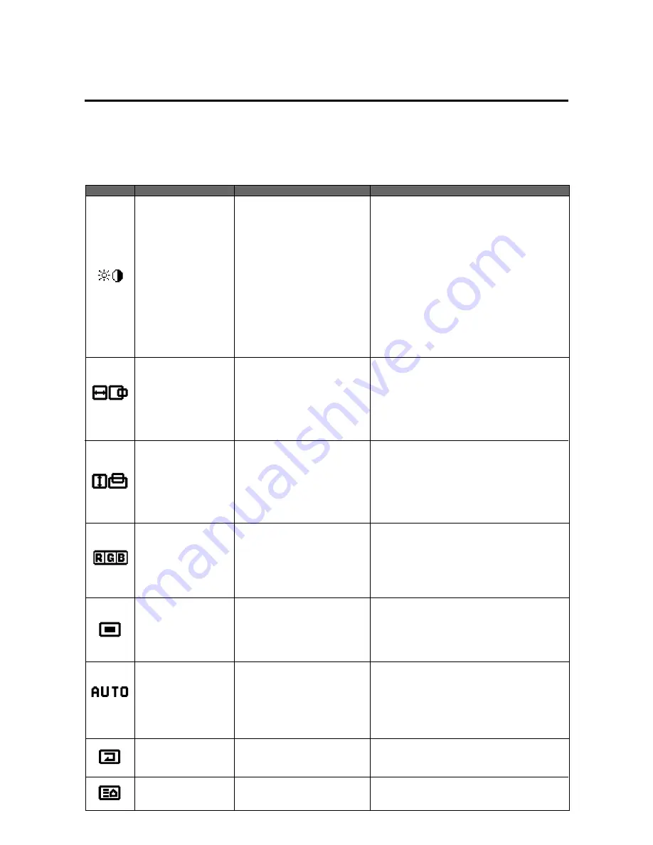
List of Setting Details

Icon

On-screen menu

Sub menu

Adjustment details

Visual Control

Image adjustment (The display will differ between video
input selection and RGB input selection.)

Brightness adjustment
Contrast adjustment
Adjustment of the saturation of the colors
Tint adjustment
Sharpness adjustment
Adjustment of the gamma characteristics
(Adjusts the brightness of dark portions)

Brightness adjustment
Contrast adjustment
Adjustment of the gamma characteristics
(Adjusts the brightness of dark portions)

At time of video input selection
Brightness
Contrast
Color
Tint
Sharpness
Gamma

At time of RGB input selection
Brightness
Contrast
Gamma

H-Position

H-Position 1

H-Position 2

H-Width

Horizontal position 1
Used to align the raster on the PDP
Horizontal position 2

Only needs to be adjusted when H-Position 1 does
not allow the complete image to fill the screen. (Ad-
justment is not required with a standard signal.)

Horizontal enlargement ratio adjustment (Only for
Multiple Screens)

V-Position

V-Position 1

V-Position 2

V-Height

Vertical position 1
Used to align the raster on the PDP
Vertical position  2

Only needs to be adjusted when V-Position 1 does
not allow the complete image to fill the screen. (Ad-
justment is not required with a standard signal.)

Vertical enlargement ratio adjustment (Only for Multi-
ple Screens)

Color Temp

Color temperature adjustment
High
Low
White balance adjustment
White balance adjustment of bright images (high bright-
ness)
White balance adjustment of dark images (dark colors)

High
Low
At time of USER selection
Gain

Bias

OSM Location

On-screen adjustment
On-screen horizontal position adjustment
On-screen vertical position adjustment
On-screen angle setting (Horizontal and vertical dis-
play)
On-screen display OFF time setting

OSM H-Position
OSM V-Position
OSM Angle

OSM Display Time

Auto Picture

Auto Picture

INPUT MODE
RGB MODE
Picture ADJ
Fine Picture
WIDE MODE

Used to automatically adjust the clock frequency and
clock phase in personal computer screen adjustment.
Signal discrimination
RGB MODE setting
Clock frequency adjustment
Clock phase adjustment
WIDE MODE setting

Normal

All Visual Normal
All Raster Normal
All Normal

Visual setting reset
Raster setting reset
Visual/Raster setting reset

Next page

Содержание PlasmaSync 42PD2

Страница 1: ...User s Manual ...

Страница 2: ...ces the plasma dis play panels with more than 99 99 percent active cells there may be some cells that do not produce light or remain lit For operating safety and to avoid damage to the unit read carefully and observe the following instructions To avoid shock and fire hazards 1 Provide adequate space for ventilation to avoid inter nal heat build up Do not cover rear vents or install in a closed cab...

Страница 3: ...ces Certain operating conditions such as the continuous display of a static image over a prolonged period of time can result in phosphor burn if proper precautions are not taken To pro tect your investment in this NEC PlasmaSync monitor please adhere to the following guidelines and recommen dations for minimizing the occurrence of image burn Always enable and use your computer s screen saver funct...

Страница 4: ...ng the Image Adjustments to the Factory Default Settings NORMAL E 22 Adjustment of the Display Menu Control List of Setting Details E 23 Before Making Adjustments E 24 To Reset the Adjustment Value to the Factory Default Setting During the Setting E 25 Adjustment of the Image Visual Controls E 27 Adjustment of Screen Position Horizontal E 28 Adjustment of Screen Position Vertical E 29 Color Temper...

Страница 5: ...ed NEC authorized serviceman Failure to follow correct mounting procedures could result in damage to the equipment or injury to the user or installer Product warranty does not cover damage caused by improper instal lation Failure to follow these recommenda tions could result in voiding your warranty Notice Installation of only the main unit is not possible Be sure to use and install the main unit ...

Страница 6: ... control functions to be made ex ternally ID No settings can be made for up to 256 units NTSC PAL SECAM and M NTSC composite video signals can be accommodated Video signals from video cameras video decks video disc players and other video equipment adhering to NTSC as well as PAL SECAM and M NTSC with a 4 43 MHz chroma signal standards can be selected on screen Varied set of input connectors Video...

Страница 7: ...ut mode Select the appropriate RGB input or video input 8 Adjust the screen Make adjustments when adjustment of the screen display position or distortion is required 9 Adjust the image Make adjustments when adjustment of the tint bright ness or contrast is required Setup Procedure Warning For proper installation and mounting it is strongly recom mended to use a trained authorized NEC dealer Failur...

Страница 8: ...e top hook and insert it into the hole Hook Attaching the Remote Control Holder Insert the top hook of the remote control holder into the installation hole of the main unit and then insert the bot tom hook into its respective hole To remove the remote control holder first release the bot tom hook then release the top hook 1 2 Housing the Remote Control in the Remote Control Holder First insert the...

Страница 9: ...ed with the RGB input connector Toggle switches between RGB1 RGB2 RGB3 Functions as the button in the on screen display OSM mode 5 UP button Functions as the button in the on screen display OSM mode 6 DOWN button Functions as the button in the on screen display OSM mode 7 PROCEED button Sets the on screen display OSM mode and displays the on screen menu 8 EXIT button Exits the on screen display OS...

Страница 10: ...rol panel do not function 14 15 16 17 18 15 VIDEO IN BNC connector BNC Inputs the video com posite video signal IN S connector DIN 4 pin Inputs the S video Y C separate signal When connections are made to both the BNC connec tor and the S video connector the signal of the S video connector has priority THROUGH OUT BNC connector BNC Outputs the same signal connected to the VIDEO IN BNC THROUGH OUT ...

Страница 11: ...Adjustment 3 POSITION CONTROL buttons Used for screen position adjustment and on screen manager OSM mode adjustment settings 4 POSITION CONTROL buttons Enable item selection and adjustments settings ON SCREEN Screen and ImageAdjustment via Menu Control 5 PROCEED button Displays the main menu of screen and image adjust ments Press this button during the display of the main menu to go to the sub men...

Страница 12: ...ts to the default factory visual settings 13 RASTER NORMAL button Returns the screen adjustments to the default factory raster settings 14 ID SELECT Selects the ID number of each monitor in a video wall so that each monitor can be adjusted with the remote control one at a time 15 CLEAR Deletes the ID number that was set with ID SELECT 16 Remote control transmitter Transmits the remote control sign...

Страница 13: ... direct sun light or strong artificial light or if there is an obstacle between the sensor and the remote control unit Note Do not connect the wired remote control to the REMOTE THROUGH OUT jack If doing so the remote control does not work Remote Control Cable To Remote Jack POWER ON POWER OFF RGB 1 RGB 2 POSITION CONTR OL RGB 3 EXIT PROCEED VIDEO CONTRAST RGB VIDEO BRIGHT COLOR VIDEO TINT SHARPNE...

Страница 14: ...een display OSM Set to ON when performing adjustments and viewing displays with the on screen display Set to OFF when displays are not desired No 2 On off switching of wireless remote control When using multiple units under wireless remote control operation the remote control signal also enters other monitors and may control them at the same time Monitors for which the reception of the wireless re...

Страница 15: ...input The image will be displayed immediately upon the input of the horizontal sync signal Suspend mode The suspend mode is set when the vertical sync signal from the personal computer is not input The image will be displayed about 4 seconds after the input of the vertical sync signal Off mode This unit is set to the off mode when the horizontal vertical sync signals from the personal computer are...

Страница 16: ...eo copy stand or Multimedia application RGBcable Supplied To mini D SUB 15 Pin input To R G B H CS V inputs BNC To VIDEO IN inputs Pin adapter for Macintosh not supplied RGBcable Supplied To mini D SUB 15 Pin input To EXTERNAL CONTROL mini D SUB 15 Pin input External equipment e g Personal computer To RGB3 DVI 29pin not supplied Personal computer with a digital RGB TMDS output HIR OYUK AIZASUSUSUS...

Страница 17: ...connector on the back of your VCR DVD or laser disc player connect the other and to the VIDEO input terminal BNC type of the monitor NOTE You will need a BNC to RCA adapter not included to connect a video cable with an RCA pin jack to the BNC input terminal of the PlasmaSync monitor 3 Turn on the monitor and the VCR DVD or laser disc player Note Refer to your VCR or laser disc player own er s manu...

Страница 18: ... S VIDEO to the external equipment When using the RGB2 Input THROUGH OUT Connections 1 To pass the RGB2 signal connect the THROUGH OUT RGBH V RGBCS to the external equipment Note Plug and Play is not available for the RGB2 BNC terminals Note In order to make sure that there is no signal loss do not loop out to more than 3 other devices maximum 4 units when taking the first unit into con sideration...

Страница 19: ...input is used the mode of the power management function can only be in the off state In the absence of TMDS signal input the unit will be in the off state The DVI standard DMPM Active off power state is equivalent to this The picture will be projected about 4 seconds after the TMDS signal input returns 3 Adjust The Raster or The Picture Control You can adjust the raster such as the horizontal size...

Страница 20: ...rn to the fac tory default setting At this time the following settings of the menu control will also simultaneously return to the fac tory default settings AUTO PICTURE PICTURE AD JUST FINE PICTURE H V POSITION 1 H V POSI TION 2 H WIDTH Multiple Screens only V HEIGHT Multiple Screens only and OSM location 2 A press of the PROCEED button will reset the adjustment To cancel the reset press the EXIT ...

Страница 21: ...AL NORMAL Returning the Image Adjust ments to the Factory Default Settings NORMAL The contrast brightness color tint gamma color temp and sharpness adjustments can be returned to the factory default settings At this time White Balance of the menu control will simultaneously return to the factory default setting 1 Press the VISUAL NORMAL button The verification sub menu is displayed 2 A press of th...

Страница 22: ...ge to fill the screen Ad justment is not required with a standard signal Horizontal enlargement ratio adjustment Only for Multiple Screens V Position V Position 1 V Position 2 V Height Vertical position 1 Used to align the raster on the PDP Vertical position 2 Only needs to be adjusted when V Position 1 does not allow the complete image to fill the screen Ad justment is not required with a standar...

Страница 23: ... ADJ All Reset Present Time Present Time Timer ON OFF time and mode setting Timer VIDEO WALL Menu Multiple screens settings Screen division setting Screen division position setting Screen Divider Setting Position of Divider Color System Power On Mode Power Manage External Control All Reset Color system setting Power ON mode setting Power management setting External control setting Settings reset L...

Страница 24: ...tment value of the selected item in the menu display Values return to the factory default settings When a menu is not being displayed all of the screen adjustments or all of the image adjustment items are reset There are two types of NORMAL functions one is RASTER for screen adjustments and the other is VISUAL for image adjustments POWER ON POWER OFF RGB 1 RGB 2 POSITION CONTR OL RGB 3 EXIT PROCEE...

Страница 25: ...verification sub menu is displayed VISUAL NORMAL PROCEED 2 A press of the PROCEED button will reset the adjustment To cancel the reset press the EXIT button ABOUT TO RESET PRESS PROCEED TO RESET EXIT TO CANCEL WARNING RASTER NORMAL Automatic Storage The settings values are stored automatically once the PROCEED button is pressed ...

Страница 26: ... COLOR TINT GAMMA 2 BRIGHTNESS CONTRAST SHARPNESS COLOR TINT GAMMA 2 BRIGHTNESS CONTRAST GAMMA 2 The cursor is moved up and down with the POSITION CONTROL buttons BRIGHTNESS CONTRAST SHARPNESS COLOR TINT GAMMA 2 Display Adjustment details Pressing the button Pressing the button Brightness Brightness adjustment Screen becomes darker Screen becomes brighter Contrast Contrast adjustment Image becomes...

Страница 27: ...stment Screen 1 Align the cursor with icon 2 Horizontal H adjustment screen 2 Align the cursor with the desired item The cursor is moved left and right with the POSITION CONTROL buttons The cursor is moved up and down with the POSITION CONTROL buttons H WIDTH Horizontal enlargement ratio adjustment Displayed only with Multiple Screens Adjustment is possible only in multi mode H POSITION 2 cannot b...

Страница 28: ...justment Screen 1 Align the cursor with icon 3 Vertical V adjustment screen Icon 3 2 Align the cursor with the desired item The cursor is moved left and right with the POSITION CONTROL buttons The cursor is moved up and down with the POSITION CONTROL buttons V HEIGHT Vertical enlargement ratio adjustment Displayed only with Multiple Screens Adjustment is possible only in multi mode V POSITION 2 ca...

Страница 29: ...or temperature 1 Align the cursor with icon 4 Color temperature adjustment screen Icon 4 2 Align the cursor with COLOR TEMP and set with the buttons The cursor is moved left and right with the POSITION CONTROL buttons 3 Return to the main menu EXIT Color temperature adjustment HIGH High LOW Low USER User setting POSITION CONTROL Move left Move up Move right Move down COLOR TEMP COLOR TEMP HIGH LOW...

Страница 30: ...he cursor is moved left and right with the POSITION CONTROL buttons 4 Return to the main menu EXIT POSITION CONTROL Becomes weaker Move up Becomes stronger Move down The cursor is moved left and right with the POSITION CONTROL buttons 3 Align the cursor with Gain or Bias of the sub menu then make the adjustment with the buttons while watching the screen PROCEED Color temperature adjustment screen ...

Страница 31: ...IGHT Move down The cursor is moved left and right with the POSITION CONTROL buttons 2 Align the cursor with the desired item from the sub menu and adjust Icon 5 The OSM screen can be rotated 90º counterclockwise for easy viewing in portrait mode by changing the OSM ANGLE on the menu The display will change to the main menu Another press of the button will delete the main menu and exit the adjustme...

Страница 32: ...to a shorter OFF time Move up Changes to a longer OFF time Move down Align with the inverted characters The following can be selected 5 seconds 10 seconds 30 seconds 60 seconds and 120 seconds 3 Return to the main menu The cursor is moved left and right with the POSITION CONTROL buttons OSM adjustment screen Icon 5 The factory default setting is 30 seconds To delete the main menu press the EXIT bu...

Страница 33: ... The Fine Picture adjustment may be Selecting Native Resolutions for 848 x 480 852 x 480 and 640 x 480 input signals There are two controls in the Plasma monitor OSM menus that allow you to set the monitor to display resolutions with 848 852 and 640 horizontal dots in their true resolutions When inputting an 848 x 480 signal align the cursor at the top of the OSM window Move the cursor down to WID...

Страница 34: ... the screen will appear blurry At time of RGB input MOTION Set when a scan converter or other mov ing picture has been connected STILL Set when displaying a personal computer screen DTV Set when using digital broadcast or other sources with an RGB input WIDE MODE NORMAL FULL STADIUM ZOOM Initial value NOR MAL Note that only NORMAL FULL area available in RGB mode Selecting Native Resolutions for 84...

Страница 35: ...nd right with the POSITION CONTROL buttons Normal Screen Returns the user side image data of the mode currently being input to the standard condition 1 Align the cursor with icon 7 2 Align the cursor with the desired item and press the PROCEED button The cursor is moved left and right with the POSITION CONTROL buttons Icon 7 The cursor is moved up and down with the POSITION CONTROL buttons ALL RAS...

Страница 36: ...nal Neg Pos Negative polarity Positive polarity V Pol Polarity of vertical sync Neg Pos Negative polarity Positive polarity 2 Return to the main menu Settings cannot be reset To delete the main menu press the EXIT button once more The vertical frequency that is displayed in the display mode can have a slight difference with respect to the actual vertical frequency of the connected input sig nal Ve...

Страница 37: ...f the year month day hour and minute positions and the buttons to set the numbers POSITION CONTROL Numbers go DOWN Cursor moves in the reverse direction Number go UP Cursor moves in ordered direction Setting range of date and time settings Year 1999 to 2099 Month JAN to DEC Day 01 to 31 Hours 00 to 24 Minutes 00 to 59 PROCEED PRESENT TIME DATE 1999 DEC 10 TIME 22 30 SET TIMER OFF PRESENT TIME DATE...

Страница 38: ... DEC 10 TIME 22 30 SET TIMER OFF PRESENT TIME DATE 1999 DEC 10 TIME 22 30 SET TIMER ON PRESS PROCEED FOR PROGRAM MENU PROGRAM MENU DATE OCT30 JAN01 MON WED THU ON 10 10 22 15 15 45 09 00 08 15 13 30 21 00 OFF 13 00 24 00 19 00 11 00 10 00 14 30 22 00 MODE VIDEO INV VIDEO RGB1 RGB2 VIDEO RGB1 1 DIRECT 2 DAILY 3 WEEKLY 3 Press PROCEED to enter the PROGRAM MENU 5 Press PROCEED to select either DIRECT...

Страница 39: ...ervals of 3 seconds 8 Use the bottons select the ON timer hour and set with the buttons Next use the bottons to select the ON time minute and set with the bottons Move onto the OFF time and perform the functions as with the ON time Auto Timer Screen PROGRAM MENU DATE OCT30 JAN01 MON WED THU ON 10 10 22 15 15 45 09 00 08 15 13 30 21 00 OFF 13 00 24 00 19 00 11 00 10 00 14 30 22 00 MODE VIDEO INV VI...

Страница 40: ...s to change the setting between 1 4 in toggle fashion The initial value is 1 POSITION CONTROL Move up Move down 3 Align the cursor with POSITION OF SETTING and set with the buttons Nothing will be displayed when 1 is selected in the SCREEN WALL MENU When 4 is selected the icon of the right screen is displayed Use the right cursor button to go clockwise and select screen 1 from among the 4 screens ...

Страница 41: ...bed below COLOR SYSTEM AUTO 3 58 NTSC PAL SECAM 4 43 NTSC Initial value AUTO 4 Return to the main menu To delete the main menu press the EXIT button once more EXIT POWER ON MODE LAST MEM VIDEO RGB1 RGB2 RGB3 Initial value LAST MEM Last Memory POWER MANAGER This means Power management of RGB input ON OFF Initial value is OFF EXTERNAL CONTROL OFF 1 2 Initial value is OFF RS 232C can be used when 1 s...

Страница 42: ...Select 1 to 256 with the left and right buttons Initial value is ALL Displays ALL with the remote control or CLEAR button 4 Return to the main menu To delete the main menu press the EXIT button once more EXIT LONG LIFE MODE 1 LONG LIFE MODE 2 LONG LIFE MODE 3 GRAY LEVEL SET ID NO RGB3 ADJ ALL RESET OFF OFF OFF 1 ALL 1 LONG LIFE MODE 1 LONG LIFE MODE 2 LONG LIFE MODE 3 GRAY LEVEL SET ID NO RGB3 ADJ...

Страница 43: ...umbers higher than 256 is not possible A press of the remote control CLEAR button causes a reset Initial value is ALL Note When both ID numbers have been set the priority order will be as described below VIDEO WALL SET ID EXIT ID SELECT MENU VIDEO WALL NO SET NO 1 256 Numbers go DOWN Numbers go UP 1 Press the ID SELECT button of the remote control This displays the ID selection screen Press the EX...

Страница 44: ...losing curtains pointing the light in a different direction etc Use the remote control unit within 30º left and right of centrer at a diatance of 22ft Set Pin No 2 to ON Unplung the remote cable from the monitor Use the remote control to set the EXTERNAL CONTROL to OFF Set an ID number with the ID SELECT button or set the ID number to ALL Replace both batteries with new ones The front panel button...

Страница 45: ... Terminals THROUGH OUT 1 0Vp p 75 Ohms unbalanced BNC Jack Composite video signal Sync negative THROUGH OUT S VIDEO Y 1 0Vp p 75 Ohms unbalanced Sync negative C 0 28Vp p 75 Ohms unbalanced Color burst level External Control mini D SUB 15pin IN THROUGH OUT IN THROUGH OUT Open Short RS 232C Control Synchronization Range Horizontal 15 5 to 68 7 KHz automatic step scan Vertical 46 0 to 85 0 Hz automat...

Страница 46: ...burst level Video Output Terminals THROUGH OUT 1 0Vp p 75 Ohms unbalanced BNC Jack Composite video signal Sync negative THROUGH OUT S VIDEO Y 1 0Vp p 75 Ohms unbalanced Sync negative C 0 28Vp p 75 Ohms unbalanced Color burst level External Control mini D SUB 15pin IN THROUGH OUT IN THROUGH OUT Open Short RS 232C Control Synchronization Range Horizontal 15 5 to 68 7 KHz automatic step scan Vertical...

Страница 47: ...Y Y Y Y Y Y Y Y Y Y Y Y Y Y Y Y Y Y Sync polarity Ver Hor Ver Hor 1 Convert to 640 dots x 480 lines and display 2 These signals cannot be displayed in the RGB3 input mode 3 Display only 400 lines with the screen center of the vertical orientation located at the center 4 The picture will be shaky when the moving images of video games etc are input In this case set the refresh rate to 75 kHz or less...

Страница 48: ...2 13 14 15 16 17 18 19 20 21 22 23 24 25 26 27 28 29 Signal Digital T M D S Data 2 T M D S Data 2 T M D S Data 2 Shield No connection No connection DDC Clock DDC Data No connection T M D S Data 1 T M D S Data 1 T M D S Data 1 Shield No connection No connection 5V Power Ground Hot Plug Detect T M D S Data 0 T M D S Data 0 T M D S Data 0 Shield No connection No connection T M D S Clock Shield T M D ...

Страница 49: ...ns are applicable to NEC plasma monitors including 42 and 50 inch types and communications con trol from external equipment Connections Connections should be made as described below 1 Display side connector EXTERNAL CONTROL connector A maximum of 4 units can used with a cascade connection External equipment e g Personal computer 2 External equipment side connector Serial port RS 232C connector See...

Страница 50: ...ksum and RS 232C odd parity The checksum comprises the following aspects of one transmitted or received frame Command 1 Unit 1 and 2 Command 2 data length and the lower order 8 bits of the total data 2 Error Processing 1 When the communications interval is 4 ms or greater the arrival of a subsequent Command 1 will be recognized If meaningful data cannot be discerned at this time that data will not...

Страница 51: ...E 52 ...

Страница 52: ...E 53 ...

Страница 53: ...E 54 ...

Страница 54: ...E 55 ...

Страница 55: ...E 56 ...

Страница 56: ...E 57 ...

Страница 57: ...E 58 ...

Страница 58: ...E 59 ...

Страница 59: ...E 60 ...

Страница 60: ...E 61 Unit inch mm Cabinet dimensions PlasmaSync 42PD2 Model PX 42VP2G 39 3 998 23 4 595 17 432 1 4 35 8 1 4 35 8 19 85 504 08 4 5 114 4 4 112 ...

Страница 61: ...E 62 Unit inch mm Cabinet dimensions PlasmaSync 50PD1 Model PX 50VP1G 47 8 1214 28 6 727 20 8 528 1 4 35 8 1 4 35 8 25 06 636 45 5 1 129 5 0 127 ...

Отзывы: