4
Quick Start
–continued
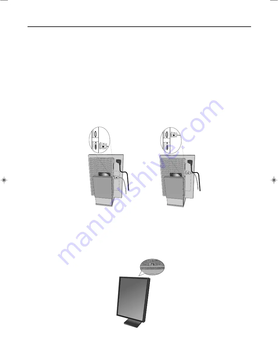
Figure D.1
Figure C.1
Figure C.2
4.
For digital input:
Connect the DVI-D signal cable to the connector on the back of the display
(Figure C.1)
.
For analog input:
Connect the 15-pin mini D-SUB signal cable (not included) to the connector on the back of the display
(
Figure C.2
).
NOTE:
Incorrect cable connections may result in irregular operation, damage display quality/components of LCD
module, and/or shorten the module life.
5. Connect one end of the power cord to the AC inlet on the back of the display and the other end to the power outlet
(
Figure C.1
). Replace the cable cover.
NOTE:
Refer to the Display Adjustment & Mounting section to check tilt, raise and lower display screen and screen
rotation when you manage cables and power cord.
NOTE:
Please refer to the Power Cord Important Information section of this manual for proper selection of AC power
cord.
6. Collect cables and power cord and place them under the cable clip (
Figure B.1
).
NOTE:
Release the cables from the clip before removing the cable cover.
7. Turn on the display with the power switch on the top (portrait) or left side (landscape) of the display
(Figure D.1)
.
Turn on the computer.
NOTE:
DO NOT switch on/off repeatedly.
8. For further adjustments, please refer to the OSM section for a full description of OSM controls.
NOTE:
If you have any problems, refer to the Troubleshooting section.
NOTE:
External equipment intended for connection to signal input, signal output, or other connectors, must comply
with the relevant IEC standard.
01_MD21GS2MPINSTALL_EN.P65
14/10/2004, 22:33
4


