background image

3

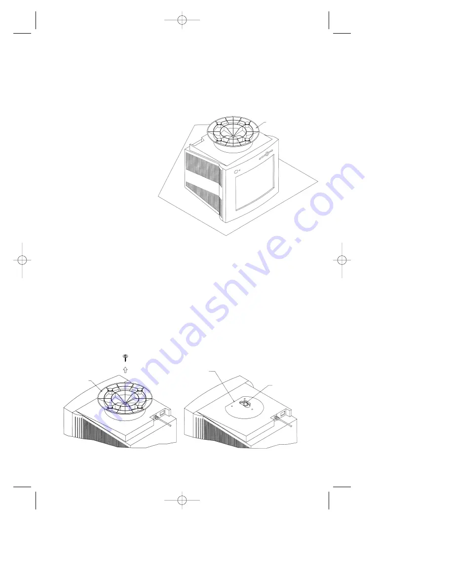
Step 2

Using a Phillips screwdriver, remove the screw securing the original
base to the monitor as shown in Figure 2A. Remove and save the
original base for possible future use.

Note:

Do not remove the spindle or swivel plate.

Figure 2A

MultiSync

®

Monitor Model Names

MultiSync 50, MultiSync 70, XV15 and XV15+

Step 1

With the monitor
unplugged from your
system and the wall
outlet, carefully
turn the monitor
upside down on
a firm table so that
the base is facing
up as shown
in Figure 1.

Figure 1

MONITOR IN POSITION TO

REMOVE THE BASE AND ATTACH

INTELLIBASE USB HUB AND AUDIO

BASE

SWIVEL
PLATE

SPINDLE

DO NOT REMOVE SPINDLE OR

SWIVEL PLATE

BASE

 203 Eng Fr Cndn manual  12/21/98 11:19 AM  Page 7

Содержание IBUSBAUD

Страница 1: ...MultiSync IntelliBase USB Hub and Audio User s Manual MultiSync IntelliBase USB Hub and Audio User s Manual 203 Eng Fr Cndn manual 12 21 98 11 19 AM Page 1 ...

Страница 2: ...ifications 24 Troubleshooting 25 References 26 Limited Warranty 27 Table des matières Contenu 31 Démarrage rapide 32 50 Tableau de commande IntelliBasemc 51 Commandes 52 Caractéristiques 54 Dépannage 55 Références 56 Garantie limitée 57 203 Eng Fr Cndn manual 12 21 98 11 19 AM Page 2 ...

Страница 3: ...convenience receptacles and the point where they exit from the appliance Image and Sound Adjust the sound output for optimal image and speaker clarity Grounding or Polarization Precautions should be taken so that the grounding or polarization means of an appliance is not defeated Cleaning The appliance should be cleaned only with a polishing cloth or a soft dry cloth Never clean with furniture wax...

Страница 4: ...rference by one or more of the following measures a Reorient or relocate the receiving antenna b Increase the separation between the equipment and receiver c Connect the equipment to an outlet on a circuit different from that to which the receiver is connected d Consult your dealer or an experienced radio TV technician for help If necessary the user should contact the dealer or an experienced radi...

Страница 5: ... the Internet at http www prodreg com nec Registration Card Im portan t To help us in our continuing efforts to better serve and support you and to bring you new and innovative products please take a few mom ents to register your new NEC MultiS ync monitor By returning this card we confirm your date of purchase and records the model and serial numbers This facilitates our ability to process warran...

Страница 6: ...OR PAST THE FIRST STOP AS THE MONITOR MAY BECOME UNSTABLE CAUSING POSSIBLE INJURY If you have any questions or comments please contact NEC at 1 800 632 4662 To attach the IntelliBase to your MultiSync brand monitor the original base must first be removed Depending on the model of your MultiSync brand monitor the removal procedure of the original base and the attachment of the IntelliBase will vary...

Страница 7: ...c Monitor Model Names MultiSync 50 MultiSync 70 XV15 and XV15 Step 1 With the monitor unplugged from your system and the wall outlet carefully turn the monitor upside down on a firm table so that the base is facing up as shown in Figure 1 Figure 1 MONITOR IN POSITION TO REMOVE THE BASE AND ATTACH INTELLIBASE USB HUB AND AUDIO BASE SWIVEL PLATE SPINDLE DO NOT REMOVE SPINDLE OR SWIVEL PLATE BASE 203...

Страница 8: ...Hub and Audio to your system 4 Figure 2C Step 3 Locate Adapter Plate A that is supplied with the IntelliBase and secure it to the spindle using the screw that was removed in Step 2 as shown in Figure 2B Figure 2B GUIDE SPINDLE THROUGH CENTER HOLE ON ADAPTER PLATE A ADAPTER PLATE A SPINDLE INTELLIBASE BOTTOM VIEW ROTATE ADAPTER PLATE UNTIL IT ALIGNS WITH THROUGH HOLES ON THE BASE 203 Eng Fr Cndn ma...

Страница 9: ...ble so that the base is facing up as shown in Figure 1 Step 2 Using your thumbs push on the locking tabs while pulling forward and up as shown by the directional arrow in Figure 3A This action releases the base from the monitor Remove and save the original base for possible future use Figure 3A Figure 1 MONITOR IN POSITION TO REMOVE THE BASE AND ATTACH INTELLIBASE USB HUB AND AUDIO BASE BASE LOCKI...

Страница 10: ...with the IntelliBase and secure it to the spindle using the screw and black nylon washer that was removed in Step 2 as shown in Figure 3C BASE ADAPTER PLATE B NEW MOUNTING Figure 3C Step 5 After the adapter plate has been attached to the base snap the base assembly to the monitor To accomplish this position all the locking tabs on the base so they mate with the holes in the monitor Slide the base ...

Страница 11: ...NITOR UNIT ONLY ADJUST THE TILT FROM THE FRONT OF THE UNIT BY HOLDING ONTO THE LEFT AND RIGHT SIDE OF THE MONITOR TILTING EITHER UPWARDS OR DOWNWARDS DO NOT TILT THE MONITOR DOWNWARDS MORE THAN 5 DEGREES OR FORCE THE MONITOR PAST THE FIRST STOP AS THE MONITOR MAY BECOME UNSTABLE CAUSING POSSIBLE INJURY If you have any questions or comments please contact NEC at 1 800 632 4662 Step 1 With the monit...

Страница 12: ...driver remove the screw securing the two base halves together as shown in Figure 4B Retain the screw and black nylon washer for use in the next step Figure 4B ORIGINAL MOUNTING RETAIN THESE PARTS TO USE IN NEW MOUNTING Step 4 Locate Adapter Plate B that is supplied with the IntelliBase and secure it to the spindle using the screw and black nylon washer that was removed in Step 3 as shown in Figure...

Страница 13: ... Step 2 attach the adapter plate assembly to the monitor To accomplish this it will be necessary to turn the adapter plate fully counter clockwise while sliding it forward as shown in Figure 4E This will allow you to install the two rear screws Figure 4E Step 7 Using the remaining screw that was removed in Step 2 complete attachment of the adapter plate assembly To accomplish this it will be neces...

Страница 14: ...IntelliBase USB Hub and Audio to your system Figure 5 Step 1 Having successfully installed your new IntelliBase carefully turn the monitor right side up as shown in Figure 5 How to connect your MultiSync monitor with IntelliBase USB Hub and Audio to your system Figure 4G INTELLIBASE BOTTOM VIEW ROTATE ADAPTER PLATE UNTIL IT ALIGNS WITH THROUGH HOLES ON THE BASE 203 Eng Fr Cndn manual 12 21 98 11 2...

Страница 15: ... adapter to the DC input jack on the rear of the IntelliBase and the other end into any 110 120V AC wall outlet as shown in Figure 7 NOTE The Intellibase front green LED power indicator should be on after this step Step 4 Reconnect your MultiSync monitor to your computer system as shown in the monitor user s manual Figure 7 USB SERIES B CONNECTOR AUDIO LINE OUTPUT SEE DETAIL A DETAIL A DETAIL B SE...

Страница 16: ...different procedure Step 5 Turn your computer on The computer will automatically recognize your IntelliBase The Add New Hardware Wizard will search for locate and install the USB Controller and Hub Device drivers needed by the IntelliBase Step 6 Click on Next button to begin driver installation 203 Eng Fr Cndn manual 12 21 98 11 20 AM Page 16 ...

Страница 17: ...13 Step 7 Select Search for the best driver for your device and then click the Next button Step 8 Click Next button to select default driver location 203 Eng Fr Cndn manual 12 21 98 11 20 AM Page 17 ...

Страница 18: ... copy the necessary files and install the drivers 14 Step 10 Insert the Windows 98 CD ROM and then click OK The required files are copied from the Windows 98 CD ROM Note Depending on system configuration this message may not appear 203 Eng Fr Cndn manual 12 21 98 11 20 AM Page 18 ...

Страница 19: ... load the USB Composite Device Step 12 Click on Next button to begin USB Composite Device driver installation Proceed to follow the screen prompts as previously completed in Steps 5 11 to complete installation of the USB Composite Device 203 Eng Fr Cndn manual 12 21 98 11 20 AM Page 19 ...

Страница 20: ...usly completed in Steps 5 11 to complete installation of the USB Human Interface Device Step 14 Click on Next button to begin USB Audio Device driver installation Proceed to follow the screen prompts as previously completed in Steps 5 11 to complete installation of the USB Audio Device 203 Eng Fr Cndn manual 12 21 98 11 20 AM Page 20 ...

Страница 21: ...plied with your IntelliBase The setup program will run automatically If the setup program does not automatically run follow Steps 17 and 18 otherwise proceed directly to Step 19 Step 17 Select the Windows Start menu and click the Run option Step 18 Type x setup exe replacing x with the drive letter of your CD ROM drive Then click the OK button 203 Eng Fr Cndn manual 12 21 98 11 20 AM Page 21 ...

Страница 22: ...ck on Next button to begin installation of the IntelliBase control panel Step 20 Upon reading and agreeing to the software license agreement click on Yes button 18 203 Eng Fr Cndn manual 12 21 98 11 20 AM Page 22 ...

Страница 23: ...tion shown or select a different location by using the Browse button 19 Step 22 Click on Next button to install the IntelliBase control panel using the default name You may also choose to rename it or to install it in an existing folder 203 Eng Fr Cndn manual 12 21 98 11 20 AM Page 23 ...

Страница 24: ...Click on Finish button to complete installation of the IntelliBase control panel The control panel icon will be added to the system tray in the lower right hand corner Software installation is now complete and you are ready to operate your IntelliBase 203 Eng Fr Cndn manual 12 21 98 11 20 AM Page 24 ...

Страница 25: ...e IntelliBase SOUND SETTINGS Used in conjunction with the Home Office button these controls are used to activate preset Treble and Bass settings tailored for specific applications MIC MUTE This control is used to mute the external microphone and stop it from recording NOTE The MIC MUTE control only mutes the microphone if it is plugged into the IntelliBase It does not control microphones plugged d...

Страница 26: ... and low power USB devices NOTE All four USB output jacks are identical and may be used interchangeably HEADPHONE OUTPUT JACK Headphones can be used to listen to audio in private When the headphone plug is inserted into the headphone jack the speakers are automatically disconnected and sound is heard through the headphones NOTE Headphones not included The headphone plug required is a mini stereo t...

Страница 27: ...ontrol is displayed in the IntelliBase control panel in the form of a slider where 0 represents minimum and 256 represents maximum Waiting for a short period or depressing the button a second time deselects the BASS function and enables the MASTER LEVEL CONTROL to be used as a volume control TREBLE When depressed and used in conjunction with the MASTER LEVEL CONTROL this button is used to increase...

Страница 28: ...Hz S N Ratio 60 dB Power Requirements AC 110 120V 60Hz Current Rating 0 4A 120V Headphone Output Impedance 32 Ohms Headphone Jack Type 3 5 mm Stereo Audio Input Jack Type 3 5 mm Stereo Microphone Input Jack 3 5mm Mono Dimensions 265 mm W x 85 mm H x 320 mm D 10 4 inches W x 3 3 inches H x 12 6 inches D Weight 1 0 kg 2 3 lbs Environmental Considerations Operating Temperature 0 to 40 C Humidity 10 t...

Страница 29: ...t plug a USB device into the rear wrong USB port must be plugged into the output ports of the IntelliBase These ports are found on the right side This USB port must be connected of the IntelliBase to the host computer There is a problem with the Verify that USB devices will work when For this check disconnect the IntelliBase host computer or software connected directly to the host computer from th...

Страница 30: ...USB Hub and Audio base information Literature Sales Info 800 NEC INFO 800 632 4636 MultiSync Fulfillment 800 820 1230 For software accessories TeleSales 800 284 4484 26 Declaration of the Manufacturer We hereby certify that the multimedia base MultiSync IntelliBase USB Hub is in compliance with the relevant clauses of IEC 65 fifth edition EN60950 1993 covering clauses 5 7 9 10 11 12 13 14 15 16 an...

Страница 31: ...27 Notes 203 Eng Fr Cndn manual 12 21 98 11 21 AM Page 31 ...

Страница 32: ...he original package or a similar package affording an equal degree of protection All Products returned to NECTECH for service MUST have prior approval which may be obtained by calling 1 800 632 4662 The Product shall not have been previously altered repaired or serviced by anyone other than a service facility authorized by NECTECH to render such service the serial number of the product shall not h...

Страница 33: ...othèque fermée qui peut gêner la circulation d air à travers les prises d air Chaleur L appareil doit être placé à l écart des sources de chaleur telles que radiateurs bouches de chaleur poêles ou autres appareils y compris les amplificateurs qui produisent de la chaleur Sources de courant Utiliser l adaptateur c a fourni L appareil doit être branché sur une prise de courant uniquement du type déc...

Страница 34: ...ère utilise et peut émettre une énergie haute fréquence et s il n est pas installé et utilisé conformément aux instructions il peut causer des interférences nuisibles aux communications radio Cependant il n y a aucune garantie que les interférences ne surviendront pas dans une installation particulière Si ce matériel cause effectivement des interférences nuisibles à la réception de la radio ou de ...

Страница 35: ...ents to register your new NEC MultiS ync monitor By returning this card we confirm your date of purchase and records the model and serial numbers Th is facilitates our ability to process warranty claims especially if your original proof of purchase is lost Th ank you for your tim e and for choosing an NEC MultiS ync monitor THANK YOU FOR CHOOSING AN NEC MultiSync IntelliBase P R O D U C T R E G I ...

Страница 36: ...RCER LE MONITEUR AU DELÀ DE LA PREMIÈRE BUTÉE CAR LE MONITEUR POURRAIT DEVENIR INSTABLE CAUSANT ÉVENTUELLEMENT DES BLESSURES Pour toute question ou tout comentaire prière de contacter NEC au 1 800 632 4662 La base d origine doit d abord être déposée afin de fixer l IntelliBase au moniteur de marque MultiSync Le mode de dépose de la base d origine et la fixation de l IntelliBase varieront en foncti...

Страница 37: ...dèles de moniteurs MultiSync MultiSync 50 MultiSync 70 XV15 et XV15 Étape 1 Le moniteur étant débranché du système et de la prise de courant renverser soigneusement le moniteur sur une table solide de manière à ce que la base soit dirigée vers le haut comme illustré à la Figure 1 Figure 1 MONITEUR EN POSITION POUR RETIRER LA BASE ET FIXER LE MOYEU USB INTELLIBASE AVEC AUDIO BASE PLAQUE PIVOTANTE A...

Страница 38: ...tème Figure 2C Étape 3 Repérer la plaque adaptatrice A fournie avec l IntelliBasemc et la fixer à l axe à l aide de la vis qui a été déposée à l étape 2 comme illustré à la Figure 2B Figure 2B GUIDER L AXE À TRAVERS LE TROU CENTRAL DE LA PLAQUE ADAPTATRICE A PLAQUE ADAPTATRICE A AXE INTELLIBASE VUE DEPUIS LE BAS FAIRE TOURNER LA PLAQUE ADAPTATRICE JUSQU À CE QU ELLE SOIT ALIGNÉE SUR LES TROUS DE P...

Страница 39: ...e vers le haut comme illustré à la Figure 1 Étape 2 À l aide de ses pouces pousser sur les pattes de blocage tout en tirant vers l avant et vers le haut comme illustré par la flèche directionnelle à la Figure 3A Cette action détache la base du moniteur Déposer et conserver la base d origine en vue d une éventuelle utilisation future Figure 3A Figure 1 MONITEUR EN POSITION POUR RETIRER LA BASE ET F...

Страница 40: ...B fournie avec l IntelliBasemc et la fixer à l axe à l aide de la vis et de la rondelle en nylon noir qui ont été déposées à l étape 2 comme illustré à la Figure 3C BASE PLAQUE ADAPTATRICE B NOUVEAU MONTAGE Figure 3C Étape 5 Une fois la plaque adaptatrice fixée à la base enclencher l ensemble de base au moniteur À cette fin positionner toutes les pattes de blocage sur la base de manière à les asso...

Страница 41: ...PPAREIL EN TENANT LES CÔTÉS GAUCHE ET DROIT DU MONITEUR PUIS EN INCLINANT VERS LE HAUT OU VERS LE BAS NE PAS INCLINER LE MONITEUR VERS LE BAS DE PLUS DE 5 DEGRÉS ET NE PAS FORCER LE MONITEUR AU DELÀ DE LA PREMIÈRE BUTÉE CAR LE MONITEUR POURRAIT DEVENIR INSTABLE CAUSANT ÉVENTUELLEMENT DES BLESSURES Pour toute question ou tout comentaire prière de contacter NEC au 1 800 632 4662 Étape 1 Le moniteur ...

Страница 42: ...einte cruciforme retirer la vis retenant les deux moitiés de base ensemble comme illustré à la Figure 4B Conserver la vis et la rondelle en nylon noir pour utilisation à l étape suivante Figure 4B MONTAGE D ORIGINE CONSERVER CES PIÈCES POUR UTILISATION DANS LE NOUVEAU MONTAGE Étape 4 Repérer la plaque adaptatrice B fournie avec l IntelliBasemc et la fixer à l axe à l aide de la vis et de la rondel...

Страница 43: ...ape 2 fixer l ensemble de plaque adaptatrice au moniteur À cette fin il faudra tourner la plaque adaptatrice entièrement en sens anti horaire tout en la faisant glisser vers l avant comme illustré à la Figure 4E Ceci vous permettra de poser les deux vis arrière Figure 4E Étape 7 En utilisant la vis restante qui a été retirée à l étape 2 terminer la fixation de l ensemble de plaque adaptatrice À ce...

Страница 44: ...B IntelliBase et Audio à votre système Figure 5 Étape 1 Une fois la nouvelle IntelliBase posée remettre soigneusement le moniteur à l endroit comme illustré à la Figure 5 Raccordement du moniteur USB de MultiSync IntelliBase avec Audio à votre système Figure 4G INTELLIBASE VUE DEPUIS LE BAS FAIRE TOURNER LA PLAQUE ADAPTATRICE JUSQU À CE QU ELLE SOIT ALIGNÉE SUR LES TROUS DE PASSAGE DE LA BASE 203 ...

Страница 45: ...trée c c située à l arrière de l IntelliBase et l autre extrémité dans n importe quelle prise de courant 110 120 V c a comme illustré à la Figure 7 REMARQUE La DEL verte de tension à l avant de l IntelliBase doit être allumée après cette étape Étape 4 Rebrancher le moniteur MultiSync à votre système informatique comme illustré dans le manuel d instructions du moniteur Figure 7 CONNECTEUR USB SÉRIE...

Страница 46: ...océdure différente Étape 5 Mettre l ordinateur sous tension L ordinateur reconnaîtra automatiquement votre IntelliBasemc L Add New Hardware Wizard recherchera repérera et installera les lecteurs du contrôleur USB et du dispositif de moyeu dont l IntelliBase a besoin Étape 6 Cliquer sur le bouton Next pour commencer l installation du lecteur 203 Eng Fr Cndn manual 12 21 98 11 22 AM Page 46 ...

Страница 47: ...sélectionner l emplacement implicite du lecteur Étape 7 Sélectionner Search for the best driver for your device Rechercher le meilleur lecteur pour votre dispositif puis cliquer sur le bouton Next 203 Eng Fr Cndn manual 12 21 98 11 22 AM Page 47 ...

Страница 48: ...es fichiers nécessaires et installera les lecteurs Étape 10 Insérer le CD ROM Windows 98 puis cliquer sur OK Les fichiers nécessaires sont copiés du CD ROM Windows 98 Remarque Suivant la configuration du système ce message peut ne pas apparaître 203 Eng Fr Cndn manual 12 21 98 11 22 AM Page 48 ...

Страница 49: ...ispositif composé USB Étape 12 Cliquer sur le bouton Next pour commencer l installation du lecteur du dispositif composé USB Suivre les sollicitations à l écran comme exécuté précédemment aux étapes 5 à 11 pour terminer l installation du dispositif composé USB 203 Eng Fr Cndn manual 12 21 98 11 22 AM Page 49 ...

Страница 50: ...emment aux étapes 5 à 11 pour terminer l installation du dispositif d interface humaine USB Étape 14 Cliquer sur le bouton Next pour commencer l installation du lecteur du dispositif audio USB Suivre les sollicitations à l écran comme exécuté précédemment aux étapes 5 à 11 pour terminer l installation du dispositif audio USB 203 Eng Fr Cndn manual 12 21 98 11 22 AM Page 50 ...

Страница 51: ...liBase Le programme d installation s exécutera automatiquement Si le programme d installation ne s exécute pas automatiquement suivre les étapes 17 et 18 sinon procéder directement à l étape 19 Étape 17 Sélectionner le menu Windows Start et cliquer sur l option Run Étape 18 Taper x setup exe en remplaçant x par la lettre de votre lecteur de CD ROM Cliquer en suite sur le bouton OK 203 Eng Fr Cndn ...

Страница 52: ...le bouton Next pour commencer l installation du tableau de commande IntelliBasemc Étape 20 Après avoir lu et accepté le contrat de licence du logiciel cliquer sur le bouton Yes 203 Eng Fr Cndn manual 12 21 98 11 22 AM Page 52 ...

Страница 53: ...trée ou séctionner un emplacement différent à l aide du bouton Browse Étape 22 Cliquer sur le bouton Next pour installer le tableau de commande IntelliBase à l aide du nom implicite On peut également choisir de le renommer ou de l installer dans un fichier existant 203 Eng Fr Cndn manual 12 21 98 11 22 AM Page 53 ...

Страница 54: ...er sur le bouton Finish pour terminer l installation du tableau de commande IntelliBase L icône du tableau de commande sera ajoutée au bac système dans le coin inférieur droit L installation du logiciel est maintenant terminée et vous êtes prêt à utiliser votre IntelliBase 203 Eng Fr Cndn manual 12 21 98 11 22 AM Page 54 ...

Страница 55: ...avec le bouton Home Office ces commandes servent à activer les réglages préalablement définis Aigus et Basses adaptés à vos applications particulières ASSOURDISSEMENT MICROPHONE Cette commande sert à assourdir le microphone externe et à l empêcher d enregistrer REMARQUE La commande ASSOURDISSEMENT MICROPHONE n assourdit le microphone que s il est branché dans l IntelliBase Elle ne contrôle pas les...

Страница 56: ... et haute puissance aussi bien que basse puissance REMARQUE Les quatre prises de sortie USB sont identiques et elles peuvent être utilisées de manière interchangeable PRISE DE SORTIE DU CASQUE D ÉCOUTE On peut utiliser un casque d écoute pour une écoute privée Lorsque la fiche du casque d écoute est insérée dans la prise du casque d écoute les haut parleurs sont débranchés automatiquement et le so...

Страница 57: ...t allumé La position relative de la commande BASSES est affichée sur le tableau de commande de l IntelliBase sous forme d une glissière où 0 représente le minimum et 256 représente le maximum Le fait d attendre brièvement ou d appuyer sur le bouton une seconde fois désélectionne la fonction BASSES et active la COMMANDE NIVEAU PRINCIPAL pour utilisation comme réglage du volume AIGUS Lorsqu il est e...

Страница 58: ...ur sortie complète Réponse de fréquence 80 Hz 20 kHz Rapport signal bruit 60 dB Alimentation nécessaire 110 120 V c a 60 Hz Courant nominal 0 4 A à 120 V Impédance de sortie du casque d écoute 32 Ohms Type de prise du casque d écoute 3 5 mm stéréo Type de prise d entrée audio 3 5 mm stéréo Prise d entrée du microphone 3 5 mm mono Dimensions 265 mm La x 85 mm H x 320 mm P 10 4 po La x 3 3 po H x 12...

Страница 59: ... Baisser le niveau du volume sur l IntelliBase ou en utilisant le logiciel du tableau de commande GUI Mettre la commande d équilibre à la position centrale en utilisant le logiciel du tableau de commande GUI S assurer que les deux extrémités du câble USB sont bien calées ou essayer de remplacer le câble USB Les dispositifs USB raccordés à l IntelliBase doivent être branchés dans les ports de sorti...

Страница 60: ...rmations détaillées 2010304 Moyeu avec Audio USB sur la base multimédias Documentation et info commerciale 800 NEC INFO 800 632 4636 MultiSync Fulfillment 800 820 1230 Pour logiciels et accessoires Téléventes 800 284 4484 Déclaration du fabricant Nous attestons par les présentes que la base multimédias MultiSync IntelliBase Moyeu USB est conforme aux clauses pertinentes de l IEC 65 cinquième éditi...

Страница 61: ... les produits renvoyés à NECTECH pour service DOIVENT faire l objet d une approbation préalable laquelle peut être obtenue en composant le 1 800 632 4662 Le produit ne doit pas avoir été altéré réparé ou entretenu précédemment par une personne autre qu un centre de service agréé par NECTECH pour rendre ce service le numéro de série du produit ne doit pas avoir fait l objet d un accident d une util...

Страница 62: ...Notes 58 203 Eng Fr Cndn manual 12 21 98 11 22 AM Page 62 ...

Страница 63: ... de NEC Technologies est interdite DÉCLARATION DE CONFORMITÉ Ce dispositif est conforme à la Partie 15 des Règles de la FCC L utilisation est sujette aux deux conditions ci après 1 ce dispositif ne peut causer des interférences nuisibles et 2 ce dispositif doit accepter toute interférence reçue y compris une interférence qui peut causer un fonctionnement non désiré Responsable aux É U NEC Technolo...

Страница 64: ...ies is prohibited DECLARATION OF CONFORMITY This device complies with Part 15 of FCC Rules Operation is subject to the following two conditions 1 This device may not cause harmful interference and 2 this device must accept any interference received including interference that may cause undesired operation U S Responsible Party NEC Technologies Inc 1250 N Arlington Heights Road Itasca Illinois 6014...

Отзывы: