background image

1. Installing Internal Optional Devices 


Express5800/T120d  User’s Guide 

66 

Chapter 2  Preparations 

1.10.4 

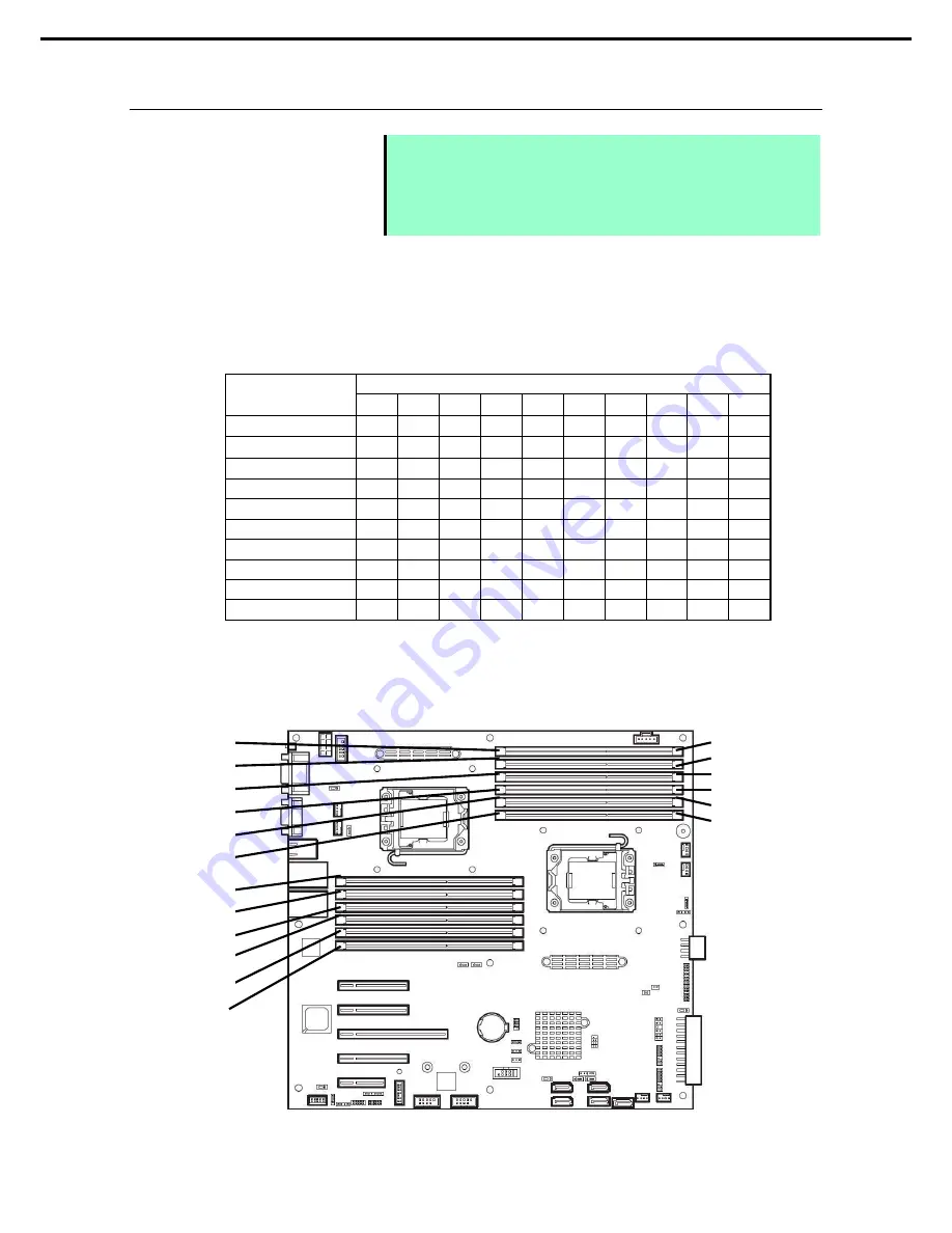
DIMM installation order 


Note 


DIMM installation order in 1-CPU configuration differs from that in 2-CPU 

configuration. 


If CPU2 is not installed, CPU2_DIMM1 to CPU2_DIMM6 are disabled. 


Refer to 

List of features supported by additiional memory board

  before 

using memory RAS feature. 


In 1-CPU configuration, install DIMMs starting from the smallest slot number. 

In 2-CPU configuration, alternately install DIMMs starting from the smallest slot number of each CPU. 

Installation order depends on combination of DIMMs to be installed.   

See the table below to find allowable combination of DIMMs, and install  DIMMs starting from the largest 
capacity and from the smallest slot number. 

N code 

N8102- 

478F 

479F 

480F 

481F 

482F 

483 

484 

485 

486 

487 

N8102-478F 


×


×


×


×


×


N8102-479F 


×


×


×


×


×


N8102-480F 


×


×


×


×


×


N8102-481F 


×


×


×


×


×


N8102-482F 


×


×


×


×


×


N8102-483 

×


×


×


×


×


×


×


N8102-484 

×


×


×


×


×


×


×


N8102-485 

×


×


×


×


×


×


×


N8102-486 

×


×


×


×


×


×


×


×


×


N8102-487 

×


×


×


×


×


×


×


×


×


: Allowed to be install together 

×

: Not allowed to be install together 


1st 
4th 
2nd 
5th 
3rd 
6th 

REAR 

FRONT 

1-CPU 

configuration 

2-CPU 

configuratio


1st 

2nd 

3rd 

4th 

5th 

6th 

7th 

8th 

9th 

10th 

11th 

12th 

Содержание Express5800/T120d

Страница 1: ...Series 10 022 01 101 01 May 2012 First Edition NEC Corporation 2012 Express5800 T120d EXP292 User s Guide Model Number N8100 1957F 1958F 1959F Chapter 1 General Description Chapter 2 Preparations Chap...

Страница 2: ...nection of peripheral devices and ideal location for this server Chapter 3 Setting Up Your Server System BIOS configurations and summary of EXPRESSBUILDER PDF Chapter 4 Appendix Specifications and oth...

Страница 3: ...e 14 Installation relocation storage and connection 15 Cleaning and working with internal devices 16 During operation 17 Warning labels 19 External view 19 Handling precautions for proper operations 2...

Страница 4: ...d boards and available slots 81 1 12 3 Installation 83 1 12 4 Removal 85 1 13 HDD Cage 86 1 13 1 Installation 86 1 13 2 Removal 91 1 14 Optical Disk Drive 93 1 14 1 Installation 94 1 14 2 Removal 95 1...

Страница 5: ...IOS Setup 140 2 1 Overview 140 2 2 Starting and Exiting SETUP Utility 140 2 2 1 Starting SETUP 140 2 2 2 Exiting SETUP 140 2 3 Description on On Screen Items and Key Usage 141 2 4 Cases that Require C...

Страница 6: ...cur Note Indicates items that must be confirmed when handling the server or operating software Tips Indicates information that is helpful to keep in mind when using this server Optical disk drives Thi...

Страница 7: ...d Windows Server 2003 R2 2 Windows Server 2003 R2 Enterprise Windows Server 2003 Standard Windows Server 2003 2 Windows Server 2003 Enterprise Windows 7 Professional 64 bit x64 Edition Windows 7 Windo...

Страница 8: ...r trademarks of Adaptec Inc of the United States LSI and the LSI logo design are trademarks or registered trademarks of LSI Corporation Adobe the Adobe logo and Acrobat are trademarks of Adobe Systems...

Страница 9: ...areil num rique de la classe A est conforme la norme NMB 003 du Canada CE Australia and New Zealand Statement This is a Class A product In domestic environment this product may cause radio interferenc...

Страница 10: ...omissions please contact your retailer 5 Regardless of these 4 items NEC Corporation does not take responsibility for effects resulting from operations 6 The sample values used in this document are no...

Страница 11: ...ARNING or CAUTION is used to indicate a degree of danger These terms are defined as follows WARNING Indicates there is a risk of death or serious personal injury CAUTION Indicates there is a risk of b...

Страница 12: ...ock or fire may be caused Do not touch the server with wet hand Otherwise an electric shock may be caused Do not touch the component specified by this symbol Otherwise an electric shock or burn may be...

Страница 13: ...sent If smoke odor or noise is present immediately turn off the server and disconnect the power plug from the outlet then contact the store where you purchased the product or your maintenance service...

Страница 14: ...le outlet by using extension cords The electric current exceeding the rated flow overheats the outlet which may cause a fire Insert the power plug into the outlet as far as it goes Heat generation res...

Страница 15: ...he server in any place other than specified Do not install the server in the following places or any place other than specified in this User s Guide Failure to follow this instruction may cause a fire...

Страница 16: ...an interface cable Do not use any damaged cable connector Do not step on the cable Do not place any object on the cable Do not use the server with loose cable connections Do not use any damaged cable...

Страница 17: ...oling fan hard disk drives only when hot plug hard disk drives are installed and power supply unit only when redundant power supply are installed support hot swapping If replacing a component when the...

Страница 18: ...server from the rack may result in personal injury and damage to nearby personal belongings Do not get yourself caught in the fan Keep your hands and hair away from the cooling fan at the rear of the...

Страница 19: ...nstallations may result in damage to the system and lead to accidents Firmly hold the bottom of the system when required to lift and carry the system To avoid the risk of personal injury be careful wh...

Страница 20: ...hat any copy protected CD that does not conform to standards will play on the server s optical disk drive In the following cases check and adjust the system clock before operation After transportation...

Страница 21: ...rom reflecting bright lights and to make the display contents easy to see Working without adjusting the display to a comfortable angle makes it difficult for you to maintain a proper posture and you w...

Страница 22: ...eatures of this server and the name of each part 1 Introduction 2 Accessories Verify the condition of your server s accessories 3 Standard Features This section describes the server s features and the...

Страница 23: ...l Pentium processor NEC s latest technology and architectures realize high power and high speed operation that cannot be matched by existing servers The server is designed with consideration of not on...

Страница 24: ...TOOL 1 Documents are stored in EXPRESSBUILDER Adobe Reader is required to read the documents so make sure you have it installed in your PC Make sure you have all accessories and inspect them If an acc...

Страница 25: ...d High speed 1000BASE T 100BASE TX 10BASE T 2 ports interface 1Gbps 100Mbps 10Mbps supported High reliability Processor throttle ring feature Memory monitoring feature error correction error detection...

Страница 26: ...upported Expandability PCI Express 3 0 x16 lanes 1 slot PCI Express 3 0 x8 lanes 2 slots 6 PCI Express 2 0 x4 lanes 1 slot x8 socket PCI Express 2 0 x1 lanes 1 slot x4 socket Large capacity memory of...

Страница 27: ...E5 2407 embedded models 2 Processor core speed depends on processor type number and type of DIMMs installed and operating voltage 1 35 1 5 V 3 N8100 1958F and N8100 1959F 4 When N8181 98 redundant fa...

Страница 28: ...fans voltage power supply and others Temperature Monitors the temperature inside of the chassis Fan Monitors the fans Voltage Monitors the voltage inside of the chassis Power supply Monitors the power...

Страница 29: ...Version Management Use of NEC ESMPRO Manager and ExpressUpdate Agent allows you to manage versions of firmware and software as well as update them by applying update packages This feature automaticall...

Страница 30: ...HDD or ODD are being accessed An amber light turns on if a HDD is broken and a light flashes green and amber alternately when a HDD is being rebuilt RAID System only 6 STATUS LED green amber This LED...

Страница 31: ...one 2 5 inch HDD cage is installed 10 Optical disk drive Either of the following drive can be installed Slim DVD ROM drive Slim DVD Super MULTI drive The drive provides the following an eject button t...

Страница 32: ...120d User s Guide 32 Chapter 1 General Description 4 3 Rear View The illustration below shows the server with optional redundant power supply unit installed 2 2 4 4 5 3 3 5 7 6 8 10 9 11 12 12 13 2 13...

Страница 33: ...feature is disabled for about 40 seconds after BMC is reset 7 Serial port COM This connector is used to connect devices that support a serial interface Note that it is not possible to directly connec...

Страница 34: ...4 Names and Functions of Parts Express5800 T120d User s Guide 34 Chapter 1 General Description 4 4 External View 1 Side Cover 1...

Страница 35: ...3 Cooling fans Rear The illustration shows when optional non redundant fan unit is installed 4 Motherboard 5 DIMM optional 6 Processor Processor is attached under the heat sink 1 Processor 1 CPU 1 2 P...

Страница 36: ...0d User s Guide 36 Chapter 1 General Description 4 6 Motherboard 1 1 2 3 4 29 5 9 8 7 27 6 10 11 0 11 1 11 2 11 3 22 12 12 13 14 15 16 17 21 18 21 19 20 31 12 32 12 21 21 21 21 21 21 23 25 24 26 28 30...

Страница 37: ...Profile Key SPI flash memory has been installed where BIOS and BMC configuration data is stored Relocate it when replacing MB to keep using the data 27 Connector for option COM 28 BMC RESET Switch Th...

Страница 38: ...cord is connected to power outlet until the server becomes ready to power on 4 7 2 STATUS LED While hardware is operating normally STATUS LED lights green STATUS LED is off or flashes green or lights...

Страница 39: ...ternal fan for dusts Also check if the fan unit is properly connected If the LED indication does not change contact your sales representative A CPU error occurred A PCI system error occurred A PCI par...

Страница 40: ...ith RAID card the indication of DISK Access LED is as shown below The DISK Access LED lights amber when disk drive is degraded However it may be shown as blinking depending on access status The DISK A...

Страница 41: ...as possible and perform reconstruction rebuild processing The failing HDD can be replaced by using hot swapping The LED flashes green and amber alternately This indicates that the HDD is being rebuil...

Страница 42: ...does not turn on in LINK state check the cable or connection SPEED LED 1 2 M This LED indicates which network interface is used Two onboard LANs 1 2 support 1000BASE T 100BASE TX and 10BASE T The LED...

Страница 43: ...s chapter describes preparations for using this server 1 Installing Internal Optional Devices You can skip this section if you did not purchase any optional devices 2 Location and Connection You must...

Страница 44: ...e the following precautions to install and remove optional devices properly and safely WARNING Be sure to observe the following precautions to use the server safety Failure to observe the precautions...

Страница 45: ...periodically touching a metal surface while working on the components Select a suitable work space Work with the server on the anti static or concrete floor If you work with the server on a carpet wh...

Страница 46: ...t off Refer to Chapter 3 6 Turning Off the Server 3 Disconnect the power cord from the outlet and the server Important After disconnecting the power cord from the server wait for at least 5 seconds be...

Страница 47: ...installation site Refer to Chapter 2 2 1 Installation 12 Install hot plug hard disk drives Refer to Chapter 2 1 22 Hot plug Hard Disk Drive 13 Attach Front Bezel Refer to Chapter 2 1 4 Removing Front...

Страница 48: ...en manipulating switches such as RESET switch using front USB connector or installing replacing hot plug hard disk drive 1 Insert the attached Bezel Lock Key into the key slot and turn the key to the...

Страница 49: ...evices Express5800 T120d User s Guide 49 Chapter 2 Preparations 3 With front bezel opened slide it upward to release the tab from the chassis frame and remove the front bezel from the server Note Be c...

Страница 50: ...ical disk drive Non hot plug HDD DIMM processor TPM module Internal Flash Memory Additional HDD cage PCI board RAID Controller Battery for RAID Controller 5 25 inch device Power supply unit Fan unit 1...

Страница 51: ...parations 1 6 Removing CPU Duct You need to remove CPU duct when installing or removing the following components DIMM Processor CPU Fan unit 1 Pull the end of two rivets to unlatch the CPU duct Note D...

Страница 52: ...1 7 1 Installation Install internal flash memory in the following procedure 1 Refer to steps 1 to 6 in Chapter 2 1 3 Overview of Installation and Removal for preparations 2 Install internal flash memo...

Страница 53: ...1 Installing Internal Optional Devices Express5800 T120d User s Guide 53 Chapter 2 Preparations 1 8 TPM Kit This section describes the procedure for installing optional TPM Kit Connector for TPM Kit...

Страница 54: ...ll TPM Kit in the following procedure 1 Refer to steps 1 to 6 in Chapter 2 1 3 Overview of Installation and Removal for preparations 2 Install TPM Kit and secure it by pushing the nylon rivet provided...

Страница 55: ...Installing a third party processor may cause a failure of the processor as well as the motherboard Repair of the server due to failures or damage resulted from installing such a processor will be cha...

Страница 56: ...before handling the CPU Do not touch the CPU pins by a bare hand or place the CPU directly on the desk For static notes refer to Chapter 2 1 2 Anti static Measures 1 Refer to steps 1 to 7 in Chapter...

Страница 57: ...gned with the key on the CPU socket Important Be sure to hold the processor only at the edges Pay attention not to touch the bottom of the processor pin section Note Insert the processor while alignin...

Страница 58: ...diagonally then tighten them securely Make sure that the screw aligns with the screw hole If not the screw may damage the motherboard 11 Make sure that the heat sink is installed on a level with the...

Страница 59: ...nue to install or remove internal optional devices mount and connect the server and turn it on 13 Run BIOS Setup Utility SETUP to confirm the following settings Refer to Chapter 3 2 System BIOS Setup...

Страница 60: ...upward and remove it 8 When removing the processor install the protective cover to the CPU socket 9 When replacing a processor install a new processor 10 If you replace the processor lightly press the...

Страница 61: ...nti static Measures Use only the specified DIMMs Installing a DIMM from a third party may damage not only the DIMM but the motherboard You will be charged to repair failures or damages caused by the u...

Страница 62: ...ing HW DEP feature Note If you are not using the HW DEP feature set Execute Disable Bit XD Bit to Disable in the BIOS settings Microsoft Windows Server 2003 R2 Standard x64 Edition Microsoft Windows S...

Страница 63: ...00MHz N8102 483 8GB additiional memory board 2x4GB R N8102 484 16GB additiional memory board 2x8GB R N8102 485 32GB additiional memory board 2x16GB R N8102 486 16GB additiional memory board 2x8GB R N8...

Страница 64: ...itiional memory board 1x4GB R N8102 480F 8GB additiional memory board 1x8GB R N8102 481F 16GB additiional memory board 1x16GB R 1333MHz 1600MHz N8102 482F 32GB additiional memory board 1x32GB R 800MHz...

Страница 65: ...Supported RAS features depend on additiional memory board See the table below for RAS features supported by additiional memory board List of features supported by additiional memory board N code Prod...

Страница 66: ...PU configuration alternately install DIMMs starting from the smallest slot number of each CPU Installation order depends on combination of DIMMs to be installed See the table below to find allowable c...

Страница 67: ...nue to install or remove internal optional devices mount and connect the server and turn it on 5 Confirm that no error messages are displayed in POST screen If any error messages are displayed refer t...

Страница 68: ...levers of the DIMM socket outward The socket is unlocked and DIMM can be removed 3 Pull out the DIMM straight 4 Confirm that no error messages are displayed on POST If any error message is displayed...

Страница 69: ...memory error multi bit error Note Refer to List of features supported by additiional memory board in 1 10 3 Memory RAS Feature before using memory RAS feature Only the features that additiional memory...

Страница 70: ...U CPU1 DIMM1 4 CPU2 DIMM1 4 is disabled To use Memory Mirroring feature install N8102 483 484 485 additional memory board two DIMMs of same model Any other memory board than N8102 483 484 485 cannot b...

Страница 71: ...ing After restart run SETUP again and check if Mirrored is displayed for the following parameter Advanced Memory Configuration Memory Information CPUx_DIMMx Status Installation order depends on CPU co...

Страница 72: ...k Step feature uses channels 2 and 3 In Memory Lock Step configuration the memory channel 1 of each CPU CPU1 DIMM1 4 CPU2 DIMM1 4 is disabled To use Memory LockStep feature x8 SDDC install N8102 483 4...

Страница 73: ...y Configuration Memory Information CPUx_DIMMx Status Installation order depends on CPU configuration See the figure below Memory Lock Step cannot be configured in the following cases Memory Lock Step...

Страница 74: ...stall N8102 486 487 additional memory board three DIMMs of same model DIMMs to be installed in sparing set must have same capacity Tips The operating system recognizes the DIMMs as those with capaciti...

Страница 75: ...Installing Internal Optional Devices Express5800 T120d User s Guide 75 Chapter 2 Preparations Memory controller Memory controller Spare set 1 Spare set 3 Spare set 5 Spare set 2 Spare set 4 Spare set...

Страница 76: ...ETUP again and check if Spared is displayed for the following parameter Advanced Memory Configuration Memory Information CPUx_DIMMx Status Installation order depends on CPU configuration See the figur...

Страница 77: ...perty such as data or other devices might be destroyed Use the battery dedicated to the RAID Controller you are using The battery is a very delicate electronic device Before installation touch the met...

Страница 78: ...a cable that comes with additional battery to the additional battery Align BLACK dot on the connectors of a Battery Control Cable and a Battery Connector on a BBU 4 Remove a single screw and remove ba...

Страница 79: ...or RAID Controller using a single screw removed in Step 2 7 Connect the cable of additional battery to RAID Controller Align BLACK dot on the connectors of a Battery Control Cable and a Battery Connec...

Страница 80: ...evice by PCI bus number device number and function number shown in the table below PCI device Bus number Device number Function number Onboard NIC1 08h 0 0 Onboard NIC2 08h 0 1 Slot 1 90h 0 X Slot 2 1...

Страница 81: ...ed together with each other Up to three or four with external RAID card can be installed Additional battery N8103 154 can be mounted Up to four additional batteries can be mounted N8103 150 RAID Contr...

Страница 82: ...x8 For additional LAN Teaming AFT SFT ALB and bonding on the same board is supported Prepare SFP module N8104 129 if needed N8104 131 10G Converged Network Adapter 2ch 10Gbps Optical PCI Express 2 0...

Страница 83: ...e battery for RAID controller is installed refer to Chapter 2 1 11 Battery for RAID Controller 1 Refer to steps 1 to 7 in Chapter 2 1 3 Overview of Installation and Removal for preparations 2 Confirm...

Страница 84: ...ction Note Make sure that the head of a PCI board bracket is seated into the fixed slot Depending on type of PCI boards the terminal part of the PCI board may be too large to fit in the connector If y...

Страница 85: ...ller N8103 149 150 151 160 For details refer to the manual that comes with optional RAID Controller N8103 149 150 151 160 Important You must avoid static electricity to work with the procedure below F...

Страница 86: ...erver can contain up to three 2 5 inch HDD cages Install cages starting from the top bay Install a 2 5 inch HDD cage in the following procedure Important If three 2 5 inch HDD cages are installed hot...

Страница 87: ...GPIO cable for connecting between HDD cages is not used When installing the second or third HDD cage use the SGPIO cable for connecting between HDD cages Connect between the first and the second cages...

Страница 88: ...cage in the following procedure 1 Refer to steps 1 to 7 in Chapter 2 1 3 Overview of Installation and Removal for preparations 2 Install two guides provided with the cage in server chassis by using tw...

Страница 89: ...for connecting between motherboard and HDD cage The SGPIO cable for connecting between HDD cages is not used When installing the second HDD cage use the SGPIO cable for connecting between HDD cages S...

Страница 90: ...stall hard disk drives in 3 5 inch fixed tray and secure the tray with four screws 4 Install 3 5 inch fixed tray to the server chassis and secure it with two screws Refer to Chapter 2 1 15 Fixed Type...

Страница 91: ...DD cage removed attach blank covers using screws Important To maintain cooling effect in the server be sure to attach blank covers 2 3 5 inch HDD cage The server can contain up to two 3 5 inch HDD cag...

Страница 92: ...emoval for preparations 2 Disconnect SAS SATA cable and power cable 3 Remove eight screws that secure 3 5 inch fixed tray 4 PUll out 3 5 inch fixed tray from the server 5 To use the server with 3 5 in...

Страница 93: ...93 Chapter 2 Preparations 1 14 Optical Disk Drive This section describes the procedure for installing the optional optical disk drive Important Do not install any unsupported optical disk drive Optica...

Страница 94: ...ons 2 Pull out the 5 25 inch device bay cover from additional slot 1 Important If an additional slot 1 contains any 5 25 inch device remove the device before installing an optical disk drive 3 Align t...

Страница 95: ...for preparations 2 Pull out the 5 25 inch device bay cover from additional slot 1 Important If an additional slot 1 contains any 5 25 inch device remove the device before removing an optical disk dri...

Страница 96: ...ptical disk drive Important Connector of optical disk drive cable has locking mechanism to prevent unintentional disconnection Push the latch on connector to unlock before removing the cable 6 Install...

Страница 97: ...allation Install fixed type hard disk drive in the following procedure 1 Refer to steps 1 to 7 in Chapter 2 1 3 Overview of Installation and Removal for preparations 2 Secure a hard disk drive to HDD...

Страница 98: ...56 00 internal SAS SATA cable Refer to Chapter 1 5 6 Motherboard for connectors on motherboard To use the hard disk drives in RAID system refer to Chapter 2 1 18 1 3 3 5 inch Fixed Type HDD cage Conne...

Страница 99: ...tions 1 16 Power Supply Unit Model N8100 1958F and N8100 1959F is hot swap redundant power supply unit 450 W or 800 W The redundant power system can be configured with two redundant power module In re...

Страница 100: ...1 Identify the failing power supply module on which AC POWER LED is lit amber or flashing amber Tips If the system is running with two power supply units thefailed power supply module can be replaced...

Страница 101: ...to 7 in Chapter 2 1 3 Overview of Installation and Removal for preparations 2 Secure the rear fan 120 mm sq to the chassis using four screws provided with non redundant fan unit and connect the fan ca...

Страница 102: ...front fan units 92 mm sq to the locations FAN1 and FAN3 enclosed with dotted line in the figure below Use the four screws two screws for one fan unit provided with non redundant fan unit to secure th...

Страница 103: ...nstallation procedure 1 17 3 Installing hot plug redundant fan unit Install redundant fan unit in the following procedure 1 Refer to steps 1 to 7 in Chapter 2 1 3 Overview of Installation and Removal...

Страница 104: ...unit in FAN3 with FAN3 connector on motherboard See the figure below Note After the front fan is installed it is difficult to connect a fan cable to motherboard Thus first connect fan cable to mother...

Страница 105: ...1 Installing Internal Optional Devices Express5800 T120d User s Guide 105 Chapter 2 Preparations 7 Change jumper switch setting on motherboard to Redundant FAN FAN FAN...

Страница 106: ...8 Arrange the CPU duct according to the figure below Tips Be sure to arrange CPU duct If not CPU duct cannot be mounted on server correctly Note Arranging CPU duct allows you to replace the hot plug...

Страница 107: ...nning CAUTION Be sure to observe the following precautions to use the server safely Failure to observe the precautions may cause burns injury and property damage For details refer to Safety precaution...

Страница 108: ...that no error messages are displayed in POST screen or STATUS LED does not show an error If any error messages are displayed refer to Chapter 3 1 POST Error Message in Maintenance Guide Tips The faile...

Страница 109: ...ring the RAID System If both PCI 1 and PCI 2 slots contain RAID cards OS is installed in hard disk drive connected to RAID Controller in PCI 2 slot Use the hard disk drive connected with RAID card in...

Страница 110: ...by referring the illustration below Use optional K410 258 00 internal SAS SATA cable to connect 2 5 inch HDD cage with motherboard Make sure the position of key pin of SGPIO cable before connection Co...

Страница 111: ...rnal SAS SATA cable are required To use 9 to 12 hard disk drives three K410 259 00 internal SAS SATA cable are required To use 13 to 16 hard disk drives four K410 259 00 internal SAS SATA cable are re...

Страница 112: ...able SATA1 SATA cable 1 SATA2 SATA cable 2 SATA3 SATA cable 3 SATA_SGPIO b When using optional RAID Controller for 3 5 inch HDD cage 1 to 8 HDDs A single 3 5 inch HDD cage can use 4 hard disk drives T...

Страница 113: ...rnal SAS SATA cable Refer to When using SW RAID for 2 5 inch HDD cage 1 to 4 HDDs for connectors on motherboard and RAID configuration jumper switch setting Connector on motherboard HDD SATA0 SATA cab...

Страница 114: ...cable that comes with optional optional K410 218 00 internal SAS SATA cable and one LED cable that comes with 3 5 inch fixed type HDD cage to connect motherboard with RAID Controller SAS SATA cable c...

Страница 115: ...have the same capacity and rotational speed If you intend to install the OS to the RAID System the process from RAID configuration to OS installation can be easily completed by using the EXPRESSBUILD...

Страница 116: ...ide 116 Chapter 2 Preparations 1 19 5 25 inch Device This section describes installation procedure for 5 25 inch device Important Do not use unsupported device Only a single internal USB device can be...

Страница 117: ...ce in the following procedure 1 Refer to steps 1 to 7 in Chapter 2 1 3 Overview of Installation and Removal for preparations 2 Pull the device bay cover toward you to remove it 3 Unlock the fixing bra...

Страница 118: ...nternal USB cable to USB2 connector on motherboard 6 Align screw holes of 5 25 inch device with those on fixing bracket and insert the end of fixing bracket into the screws holes of 5 25 inch device 7...

Страница 119: ...Installing CPU Duct Install the CPU duct after internal devices including DIMM or PCI card are installed and connected 1 Insert the CPU duct so that the swelling of CPU duct covers the stand on mothe...

Страница 120: ...luding DIMM or PCI card are installed and connected 1 Insert the guide metals front and rear 2 places located lower inside of the side cover into the frame of the server 2 Insert hooks 5 places locate...

Страница 121: ...tational speeds cannot be installed together In 2 5 inch HDD cage hard disk drives or SSD having different capacities interface types or rotational speeds can be installed together if the following co...

Страница 122: ...lot 5 SAS HDD 10K Slot 6 SAS HDD 10K Slot 0 SATA SSD Slot 1 SATA SSD Slot 2 SATA SSD Slot 3 SAS SSD Slot 4 SAS SSD Slot 5 SAS SSD Slot 6 SAS SSD Slot 7 Slot 0 SATA SSD Slot 1 SATA SSD Slot 2 SATA SSD...

Страница 123: ...te In the RAID group pack build a Disk Array using hard disk drives that have the same specifications capacity rotational speed and standard 1 Refer to Chapter 2 1 3 Overview of Installation and Remov...

Страница 124: ...ive carrier firmly with both hands 6 Slowly close the handle The drive carrier is locked making a clicking sound Note When you push the drive into the slot confirm the handle got hooked on the frame 7...

Страница 125: ...r data leakage should the product be transferred to a third party without erasing the data Note If you have to remove a disk due to a hard disk drive failure check the slot with its DISK LED lit in am...

Страница 126: ...is automatically rebuilt when hot swapping replacing a disk while the power on a failed hard disk drive During the auto rebuild the DISK LED on the hard disk drive flashes green and amber alternately...

Страница 127: ...ions 1 23 Installing the Front Bezel To install the front bezel insert three tabls on left end of front bezel into frame holes on front right side of the server and close the front bezel After install...

Страница 128: ...ppears during setup of SDR the target server is incorrect Check the server model Error incorrect server platform found To perform this work the system must be booted from CD ROM If boot device order i...

Страница 129: ...number indicated on SDR UPDATE TOOL 243 423836 502 media provided with the server If the applied SDR data differs from system configuration power off the server disconnect AC power cord and confirm ju...

Страница 130: ...e specified environment Do not connect the ground wire to a gas pipe CAUTION Be sure to observe the following precautions to use the server safely Failure to observe the precautions may cause burns in...

Страница 131: ...st free clean and organized room The environment that satisfies the following conditions Operating Storage Ambient temperature 10 C to 40 C 5 C to 40 C Humidity 20 to 80 10 to 80 Temperature gradient...

Страница 132: ...n is connected Place where intense vibration may be generated Place where some objects may be fallen Place near a device generating intense magnetic field such as TVs radios broadcast communication an...

Страница 133: ...r safety Failure to observe the precautions may cause death or serious injury For details refer to Safety precautions in Precautions for Use Do not hold the power plug with wet hands Do not connect th...

Страница 134: ...al port connector Display unit USB device USB device Rear Front 1000BASE T 100BASE TX 10BASE T Hub switching hub etc Finally connect the power cord to an outlet For connecting to the UPS refer to the...

Страница 135: ...ties Make sure that no pressure is applied on the plug of power cord 2 2 1 Connecting to a uninterruptible power supply UPS To connect the power cord of the server to the uninterruptible power supply...

Страница 136: ...gs by following the instructions in this section 3 EXPRESSSCOPE Engine 3 EXPRESSSCOPE Engine 3 provides useful features through the Baseboard Management Controller BMC 4 EXPRESSBUILDER EXPRESSBUILDER...

Страница 137: ...vices that connect to the display monitor and the server Note If the power cord is connected to power control system such as an Uninterruptible Power Supply UPS make sure that the power control system...

Страница 138: ...fter the logo appears 2 If Enabled is specified for Password On Boot in Security menu of SETUP you will be prompted to enter password after the logo is displayed If you enter the incorrect password th...

Страница 139: ...ch has its dedicated BIOS such as a RAID controller board is installed a message that prompts you to start the dedicated utility to set each board is displayed Example If an optional RAID Controller i...

Страница 140: ...sequence After a while the following message will be displayed on the lower left of the screen On screen message may differ from the one shown below depending on your environment Press F2 SETUP F3 Int...

Страница 141: ...a menu which has on the left is selected Enter key Press this key to confirm the selected parameter Esc key Cancels the pop up screen On submenu screen pressing the Esc key returns to the previous scr...

Страница 142: ...tored Load Previous Values Yes No F3 key If you press this key the following window appears If you select Yes restore the parameters of the currently selected item to the default setting This might be...

Страница 143: ...uration PCI Device Controller and Option ROM Settings PCIXX Slot Option ROM Disabled XX is PCI slot number of the option board Boot Change the boot order of devices Boot Boot Option Priorities Change...

Страница 144: ...assword 3 times operation stops You cannot operate further Turn off the power Saving changes If you finish configuration select Save Exit and then Save Changes and Exit to save changes and exit If you...

Страница 145: ...rtual Flash is always connected as USB mass storage 3 2 EXPRESSSCOPE ENGINE 3 Network configuration To enable EXPRESSSCOPE Engine 3 to be used via network network configuration is required Below is an...

Страница 146: ...ss Subnet Mask Tips If Shared BMC LAN is enabled Web feature remote media KVM feature or command line interface feature may be interrupted In this case wait for a while and connect with network again...

Страница 147: ...ture select Tool menu in the menu after boot Storage of documents Stores various documents including User s Guide Installation Guide and Maintenance Guide Documents and some software components are no...

Страница 148: ...Software Components Express5800 T120d User s Guide 148 Chapter 3 Setup 5 Installing Software Components Continue to install software components such as OS Refer to the instructions below Installation...

Страница 149: ...server is connected to a UPS refer to the documentation supplied with the UPS or the documentation for the application controlling the UPS 1 Shut down the OS 2 The server automatically turns off afte...

Страница 150: ...Express5800T120d User s Guide 150 NEC Express5800 Series Express5800 T120d Appendix 1 Specifications 2 Interrupt Lines 4 4...

Страница 151: ...2C compliant D sub 9 pin serial port A 1x Rear optional port can be used up to two ports in total 2x 1000BASE T LAN connector 1000BASE T 100BASE TX 10BASE T supported RJ45 2x Rear 1x Management LAN co...

Страница 152: ...al DVD ROM per system for maintenance and OS reinstallation purposes 2 Prepare this if required For the principal uses of a Flash FDD refer to the notes on Flash FDD in the Maintenance Guide 3 For out...

Страница 153: ...add optional devices Interrupt lines As factory settings interrupt lines are assigned as follows IRQ Peripheral Device Controller IRQ Peripheral Device Controller 0 System timer 12 1 13 Numeric data p...

Отзывы: