background image

4. Names and Functions of Parts


Express5800/R120h-1M  User’s Guide 

33


Chapter 1  General Description 

4.6 


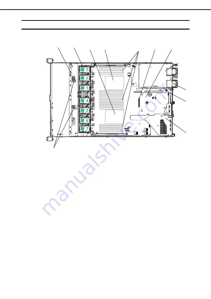
Internal View 


(1) Backplane 

(2) Cooling 

Fan 

-1  FAN1 (option) 
-2  FAN2 (option) 
-3  FAN3 
-4  FAN4 
-5  FAN5 
-6  FAN6 
-7  FAN7 
FAN3 to FAN7 are factory installed. FAN 1 and 

2 are required in 2-CPU configuration. 

(3) Processor 

(CPU) 

-1  CPU1 (required option) 
-2  CPU2 (option)


(4) DIMM 

(option) 

1 or more option(s) required per CPU 

(5)  Slot for RAID Controller (option)


(6) Motherboard 

(7)   Primary Riser Card cage 

Standard riser is standard-installed 
Changeable by option 

(8)  Secondary/Tertiary Riser Card cage (option)


(9)  Power Supply Unit 

The numbers after the parenthesized numbers 
indicate slot numbers. 
-1 PSU1 (required option) 
-2 PSU2 (optional) 

(10) Battery-holding part for RAID controller 
     (Lithium ion battery) 


(1) 

(2) 

(4) 

(9)-1 

(6) 

(8) 

(7) 

(10) 

(3)-

(5) 

(3)-2

(9)-2 

Содержание EXP804

Страница 1: ...Guide NEC Express Server Express5800 Series Express5800 R120h 1M EXP804 Chapter 1 General Description Chapter 2 Preparations Chapter 3 Setup Chapter 4 Appendix 10 201 01 101 04 July 2018 NEC Corporati...

Страница 2: ...reparations Installation of additional options connection of peripheral devices and suitable location for this server Chapter 3 Setup System utility configurations and summary of EXPRESSBUILDER Chapte...

Страница 3: ...4 1 Front View With Front Bezel 25 4 2 Front View Without Front Bezel 26 4 3 Rear View 28 4 4 External View 29 4 5 Motherboard 30 System Maintenance Switch 31 DIMM slot 32 4 6 Internal View 33 4 7 Coo...

Страница 4: ...77 1 11 Riser Card 83 Notes 83 Installing primary riser card options 83 Installing primary riser card SATA M 2 N8116 53 85 Installing primary GPU and cable options 87 Installing tertiary riser card lo...

Страница 5: ...l 150 1 25 Use of Internal Hard Disk Drives in the RAID System 151 Notes on Building RAID System 151 1 26 Installing Top Cover 152 1 27 Drives 153 Installing a SAS or SATA drive 154 Removing Hot Plug...

Страница 6: ...w 203 3 2 Comparison of License Features 204 3 3 iLO 5 Network Settings 205 4 EXPRESSBUILDER and Starter Pack 208 4 1 Features of EXPRESSBUILDER Starter Pack 208 4 2 Usage of EXPRESSBUILDER 208 4 3 Us...

Страница 7: ...mbol indicates the presence of a hazard if the instruction is ignored An image in the symbol illustrates the hazard type Prohibited Action This symbol indicates prohibited actions An image in the symb...

Страница 8: ...elpful to keep in mind when using this server Optical disk drive This server is equipped with one of the following drives These drives are referred to as optical disk drive in this document DVD ROM dr...

Страница 9: ...xpress5800 R120h 1M User s Guide 9 POST POST described in this manual refers to the following Power On Self Test BMC BMC described in this manual refers to the following Baseboard Management Controlle...

Страница 10: ...f Microsoft Corporation in the United States and other countries Intel and Xeon are registered trademarks of Intel Corporation of the United States Vmware is a registered trademark or a trademark of V...

Страница 11: ...FOR A PARTICULAR PURPOSE ARE DISCLAIMED IN NO EVENT SHALL THE COPYRIGHT HOLDER OR CONTRIBUTORS BE LIABLE FOR ANY DIRECT INDIRECT INCIDENTAL SPECIAL EXEMPLARY OR CONSEQUENTIAL DAMAGES INCLUDING BUT NO...

Страница 12: ...r the Unified Extensible Firmware Interface UEFI Forum s UEFI Specifications v 2 0 and later together the UEFI Specifications only as necessary to emulate an implementation of the UEFI Specifications...

Страница 13: ...ct includes software developed by Greg Roelofs and contributors for the book PNG The Definitive Guide published by O Reilly and Associates zlib End User License Agreement zlib License zlib h interface...

Страница 14: ...s Keep this document for future use Latest editions This document was created based on the information available at the time of its creation The screen images messages and procedures are subject to ch...

Страница 15: ...Warnings and Additions to This Document Express5800 R120h 1M User s Guide 15...

Страница 16: ...e drop may occur due to lightning strike To prevent this use of UPS is recommended In the following cases check and adjust the system clock before operation After transportation After storage After th...

Страница 17: ...en from reflecting bright lights and to make the display contents easy to see Working without adjusting the display to a comfortable angle makes it difficult for you to maintain a proper posture and y...

Страница 18: ...chapter introduces the features of this server and the name of each part 1 Introduction 2 Accessories Describes the accessories of the server 3 Features Describes the features of the server and the s...

Страница 19: ...e latest microprocessor Intel Xeon processor With our latest technology and architecture we offer high performance and high reliability that could not be accomplished by conventional servers Furthermo...

Страница 20: ...ched to Front Bezel Safety Precautions and Regulatory Notices Getting Started In addition to these enclosed items the following extra items may be required Operating system or application software Har...

Страница 21: ...16 50MB TDP 105W 9 Xeon Gold 6126 Processor 2 60 GHz 12C 24T 19 25MB TDP 125W 9 Xeon Gold 6128 Processor 3 40 GHz 6C 12T 19 25MB TDP 115W Xeon Gold 6130 Processor 2 10 GHz 16C 32T 22MB TDP 125W 9 Xeo...

Страница 22: ...38 50MB TDP 165W 9 Xeon Platinum 8180M Processor 2 50 GHz 28C 56T 38 50MB TDP 205W 9 Turbo Boost Technology feature 1 Hyper Threading Technology feature 1 Intel AVX 512 Extended Instruction Set 2 Int...

Страница 23: ...t PCI Express 3 0 x16 lanes 2 slots Low profile 8 PCI Express 3 0 x8 lanes 1 slot dedicated to RAID controller PCI Express 3 0 x8 lanes 1 slot dedicated to LOM card Large capacity memory of up to 3 0T...

Страница 24: ...es Platinum 8100 series is 3 UPI 4 The device that mounts Intel Xeon processor Bronze 3100 series Silver 4100 series is not supported 5 Operating frequency can vary depending on the type or the number...

Страница 25: ...es and Functions of Parts This section describes the names of the server parts 4 1 Front View With Front Bezel 1 Front Bezel A cover for protecting the front of the server This cover can be locked wit...

Страница 26: ...ve 7 POWER Switch LED A switch for turning on off the server Press once to turn on the server POWER LED lights when it is on Press it again to turn off the server Hold down the switch for four seconds...

Страница 27: ...rive DVD Super MULTI drive 7 POWER Switch LED A switch for turning on off the server Press once to turn on the server POWER LED lights when it is on Press it again to turn off the server Hold down the...

Страница 28: ...ess status of LAN See 4 8 2 LEDs on the backside of the unit 10 LAN connectors Connectors for connecting to a network 1000BASE T 100BASE TX 10BASE T 10 1 LAN1 connector 10 2 LAN2 connector 10 3 LAN3 c...

Страница 29: ...4 Names and Functions of Parts Express5800 R120h 1M User s Guide 29 Chapter 1 General Description 4 4 External View 1 Top cover 2 Hood latch 2 1...

Страница 30: ...Port 5 connector for optical disk drive 12 Power supply SW USB 3 0 connector 13 Battery connector for RAID controller 14 Power Connector for Expander Board 15 Power Connector for Expander Board 16 Pow...

Страница 31: ...0 Off Reserved SW11 Off Reserved SW12 Off Reserved Important Do not change the system maintenance switch that says Reserved unless it is instructed by the document It may cause the trouble or malfunct...

Страница 32: ...Names and Functions of Parts Express5800 R120h 1M User s Guide 32 Chapter 1 General Description DIMM slot DIMM slots are numbered in order 1 to 12 for the processor 2 Slot Channel The front of device...

Страница 33: ...cessor CPU 1 CPU1 required option 2 CPU2 option 4 DIMM option 1 or more option s required per CPU 5 Slot for RAID Controller option 6 Motherboard 7 Primary Riser Card cage Standard riser is standard i...

Страница 34: ...tion of server cannot be recommended The following displays the structure for installing cooling fans Configur ation Fan bay 1 Fan bay 2 Fan bay 3 Fan bay 4 Fan bay 5 Fan bay 6 Fan bay 7 1xCPU Fan cov...

Страница 35: ...es not a shutdown but a hard shutdown of OS With Thermal Shutdown function set to Disabled at BIOS Platform Configuration RBSU in case a temperature at a cautious level is detected the shut down of OS...

Страница 36: ...Power switch and system power LED 1 Lights in green The system is powered on Flashes in green once per second The power on sequence in progress Lights in amber The system is in standby state Lights of...

Страница 37: ...is in progress Lights off Not working 2 LINK ACT LED 1 Lights in green Linked to the network Flashes in green once per second The network is working Lights off The network is not working 3 STATUS LED...

Страница 38: ...servers Subsystem LED status Motherboard Flashes once Processor Flashes twice Memory Flashes 3 times Riser card board PCIe slot Flashes 4 times LOM card Flashes 5 times RAID controller SAScontroller...

Страница 39: ...ts off Normal state Lights in amber The power subsystem is degraded the power supply unit has failed or the input power is disconnected Riser Card LED Lights off Normal state Amber Riser card unit is...

Страница 40: ...not properly installed Cooling Fan LED Amber Amber Green One cooling fan has failed or has been removed Amber Red Green Two or more cooling fans have failed or have been removed Power Supply Unite LED...

Страница 41: ...T LED Lights in green Working in operation Flashes in green Working in operation Lights off Not working 3 AC POWER2 LED Lights in green Normal state Lights off One or more of the following situations...

Страница 42: ...en A drive is a member of one or more logical drives Flashes in green Rebuilding the drive migrating RAID on the drive migrating or expanding the capacity of the strip size expanding the capacity of t...

Страница 43: ...SD drive before completion of the device signal and traffic flow may result in data loss No Item Status Description 1 Release lever 2 DISK ACT LED Rotates in green Drive is working Lights off Drive is...

Страница 44: ...l option 2x2 5 inch drive SAS SATA PCIe SSD Chart number BOX number 1 BOX1 Bay 1 8 2 BOX2 Bay 1 2 Device number of 4x3 5 inch drive model SAS SATA Device number of 10x2 5 inch drive model PCIe SSD SAS...

Страница 45: ...4 Names and Functions of Parts Express5800 R120h 1M User s Guide 45 Chapter 1 General Description Device number of option rear SAS SATA Rear Option Device Bay supports 1x2 5 inch drive...

Страница 46: ...ations This chapter describes preparations for using this server 1 Installing Internal Optional Devices You can skip this section if you did not purchase any optional devices 2 Installation and Connec...

Страница 47: ...safely WARNING Be sure to observe the following precautions to use the server safety Failure to observe the precautions may cause death or serious injury For details see Safety Precautions and Regula...

Страница 48: ...switch to identify the target server See Chapter 2 1 3 Identifying Servers UID Switch Remove Front Bezel See Chapter 2 1 4 Removing Front Bezel Turn off the server See Chapter 3 6 Turning Off the Ser...

Страница 49: ...ves in the RAID System Attach Top Cover See Chapter 2 1 26 Installing Top Cover Mount the server onto the rack See Chapter 2 2 1 2 1 Installation Install hard disk drives See Chapter 2 1 27 Drives Ins...

Страница 50: ...the target server When the server is working be sure to identify the target server by using UID Switch first before you turn off the server or disconnect a cable from the server To turn UID LED on pre...

Страница 51: ...ight and unlock the lever seen on the left when you face the front bezel and pull only the left side of bezel by about 10 cm toward you Then as shown in the diagram pull the bezel to the left toward d...

Страница 52: ...lobular driver T 10 or flathead driver See steps 1 to 5 in Chapter 2 1 2 Overview of Installation and Removal for preparations Unscrew the security screw with the hexalobular driver or flathead driver...

Страница 53: ...f an OS is configured to use the TPM and it is removed the OS may go into recovery mode data loss can occur or both When installing or replacing hardware our service providers cannot enable the TPM or...

Страница 54: ...tem power Portions of the power supply and some internal circuitry remain active until AC power is removed Important To reduce the risk of personal injury from hot surfaces allow the drives and the in...

Страница 55: ...led on a different device the data including the key stored in TPM are deleted when the power is turned on the TPM that has been removed from the original server and installed on another server 6 Inst...

Страница 56: ...saved the server prompts for reboot request Press the Enter key to confirm reboot If the following actions were performed the server reboots a second time without user input During this reboot the TP...

Страница 57: ...sure to use the CPU authorized by NEC Installing a third party CPU may cause a failure of the CPU as well as the motherboard Repair of the server due to failures or damage resulted from installing suc...

Страница 58: ...are ESXi 6 5 576 112 1 When Hyper V is used the maximum number of logical processors is as shown below Windows Server 2012 R2 320 Windows Server 2016 512 Installation Please prepare the following befo...

Страница 59: ...each heatsink nut in the order indicated on the heatsink label 1 2 3 4 until it no longer turns 3 If installing a second processor install fans in bays 1 and 2 These fans are provided with the proces...

Страница 60: ...an additional fan unit provided with additional CPU kit Remove the fan blank cover from the fan bay 6 Attach the fan to bay 1 and 2 Fan connection conditions are shown in the table below Fan bay Conf...

Страница 61: ...formation and additional processor specifications follow the directions below 1 Reboot the server The server restarts and the POST screen is displayed 2 Press F9 System Utility screen appears 3 Select...

Страница 62: ...onducting the appropriate anti static treatment There is a possibility of causing electrostatic discharge if appropriate grounding wire treatment is not conducted To install the components follow thes...

Страница 63: ...server Note In order to prevent damage of the system due to improper cooling or elevated temperature please do not activate the server or enclosure without implementing any of component or blank on al...

Страница 64: ...2 5 type PCIe SSD and 10x2 5 type drive The server support change of the fan speed Run the fan at the minimum speed until the temperature rises and the server must be cooled down by increasing the fan...

Страница 65: ...ink kit T 30 hexalobular driver 1 4 flat blade screwdriver or nonconductive tool To install the components follow these steps 1 Please follow the cautions below Note The processor assembly must be rem...

Страница 66: ...nd remove 4 Turn over the heat sink module and position the contact surface of the processor at the top 5 Install the protective cover on the processor socket 4 Remove the processor from the heat sink...

Страница 67: ...Note Do not touch the point of contact of the processor 6 Remove the dust cover of the high performance heat sink 7 Align the pin mark 1 on the processor frame with the pin mark 1 on the high performa...

Страница 68: ...r heatsink assembly will only install one way Using a T 30 hexalobular screwdriver fully tighten each heatsink nut until it no longer turns Note Be sure to tighten each heatsink nut fully in the order...

Страница 69: ...ation and additional processor specifications follow the directions below 1 Reboot the server The server restarts and the POST screen is displayed 2 Press F9 key System utility screen appears 3 Select...

Страница 70: ...s reason you can provide higher system capacity and bandwidth by installing larger capacity DIMM For the information corresponding to all the types all the types are referred to as DIMM If you specify...

Страница 71: ...ots Slot number shows DIMM slot ID for spare replacement Please see the following chart for the location of the slot number The order of installation may be different on x1CPU PROC1 configuration and...

Страница 72: ...8 9 10 11 12 19 DIMM 1 3 5 7 8 9 10 11 12 1 3 4 5 6 7 8 9 10 12 20 DIMM 1 3 4 5 6 7 8 9 10 12 1 3 4 5 6 7 8 9 10 12 21 DIMM 1 3 4 5 6 7 8 9 10 12 1 3 4 5 6 7 8 9 10 11 12 22 DIMM 1 3 4 5 6 7 8 9 10 11...

Страница 73: ...5122 processor 2400MHz Xeon Silver 4100 Series Xeon Bronze 3100 Series 2133MHz The operation memory speed is decided by rating DIMM speed DIMM attached on each channel processor model and speed selec...

Страница 74: ...ption Meaning 1 Capacity 8GB 16GB 32GB 64GB 128GB 2 Rank 1R Single rank 2R Dual rank 4R Quad rank 8R Octal rank 3 DRAM data width X4 4 bit X8 8 bit X16 16 bit 4 Memory generation DDR4 5 The maximum sp...

Страница 75: ...ot Doing so can damage the socket or terminal part Continue to install remove the internal options Refer to Chapter 2 1 26 Installing Top Cover in this manual to replace the top cover Note In order to...

Страница 76: ...move DIMM To remove DIMM reverse the installation procedure Be sure to install dummy cover to the slots from where DIMMs are removed Note When removing a defective DIMM check error messages displayed...

Страница 77: ...function ADDDC Single Device Data Correction SDDC is afunction to restore the data automatically in case one of memory chips stored on DIMM breaks The mother board of this device has six systems of Me...

Страница 78: ...operating system The followings are the conditions to use this function Install 12 DIMMs per CPU Use DIMMs with the same product number for the device Change the following parameters and save them Fr...

Страница 79: ...ocessor Notes for the setting of memory mirroring Even if Mirrored Memory with Advanced ECC Support is set in Advanced Memory Protection and Memory Mirroring Configuration is selected in case DIMM con...

Страница 80: ...it changes depending on the number of DIMM installed and the capacity per one For the physical memory capacity available from the operating system refer to the table below The number of CPU The number...

Страница 81: ...nfiguration in case DIMM configuration which cannot constitute memory sparing due to expansion or removal of DIMM is detected Advanced Memory Protection operates as Advanced ECC In this case Advanced...

Страница 82: ...lled in this server Cautions for setting the fault tolerant memory ADDDC If the DIMM configuration that cannot allow the fault tolerant ADDDC configuration is detected while Fault Tolerant Memory ADDD...

Страница 83: ...nd Fingerprints and dust left on them cause the server to malfunction due to a connection failure or damage to the leads Available type of PCI card depends on the type of a riser card Make sure the ca...

Страница 84: ...ogether and insert them in with certainly 4 See Chapter 2 1 26 Installing Top Cover to attach the top cover of the server Note In order to prevent damage of the system due to improper cooling or eleva...

Страница 85: ...ssibility of causing electrostatic discharge if appropriate grounding wire treatment is not conducted Please prepare the following before installing the option Parts included in the option kit M 2 med...

Страница 86: ...mother board together and insert them in with certainly 6 See Chapter 2 1 26 Installing Top Cover to attach the top cover of the server Note In order to prevent damage of the system due to improper c...

Страница 87: ...ching Note In order to prevent the damage to electronic components please start to install the system after conducting the appropriate anti static treatment There is a possibility of causing electrost...

Страница 88: ...in with certainly 7 See Chapter 2 1 26 Installing Top Cover to attach the top cover of the server Note In order to prevent damage of the system due to improper cooling or elevated temperature please d...

Страница 89: ...hapter 2 1 2 Overview of Installation and Removal for preparations 2 Install optional secondary riser card 1 Confirm that positions of secondary riser card and the arrow mark on the power cage are cor...

Страница 90: ...becomes hot after use so to avoid burns please allow the drive and internal parts of the system to cool before touching Note In order to prevent the damage to electronic components please start to in...

Страница 91: ...s Express5800 R120h 1M User s Guide 91 Chapter 2 Preparations 3 From the primary riser card take off the screws two fixing the bracket of Slot2 and take off the bracket 4 In case a low profile bracket...

Страница 92: ...Devices Express5800 R120h 1M User s Guide 92 Chapter 2 Preparations 5 Unscrew the screw of secondary riser card latch and rift the latch upward to take it off 6 Fit a full height PCle x16 riser card...

Страница 93: ...ter 2 1 26 Installing Top Cover to attach the top cover of the server Note In order to prevent damage of the system due to improper cooling or elevated temperature please do not activate the server or...

Страница 94: ...obular driver Important The surface becomes hot after use so to avoid burns please allow the drive and internal parts of the system to cool before touching Note In order to prevent the damage to elect...

Страница 95: ...s mounted on slot 2 riser card remove PCI board After that remove 2 screws on slot 2 and remove cage bracket 5 Remove the screw which fixes on the riser card latch and lift up the riser card latch to...

Страница 96: ...PCIe x16 riser card on the position corresponding to the connector on the mother board and insert the riser card After that please connect the GPU cable to riser card connector 8 Remove the existing r...

Страница 97: ...o prevent damage of the system due to improper cooling or elevated temperature please do not activate the server or enclosure without implementing any of component or blank on all of drive bays and de...

Страница 98: ...er 1 1 8 Anti static Measures in Safety Precautions and Regulatory Notices Notes Read the following notes when installing or removing a PCI card Do not touch the terminals of the riser cards and the l...

Страница 99: ...PCI Express 3 0 x8 3 1 2 2 Maximum of up to 1 battery per device N8103 196 RAID Controller 2GB RAID 0 1 5 6 PCI Express 3 0 x8 3 1 2 2 For external device Maximum of up to 1 battery per device N8103...

Страница 100: ...es 64Gbps one way 2 Shows a connector size Cards having the number of plugs or lower can be connected Ex x8 Plug x1card x4card or x8card can be installed x16 card cannot be installed Refer to the tech...

Страница 101: ...3 Others Slot performance 1 Slot form 2 Slot size M 2 SATA SSD slot PCIe SSD connector 3 GPU power connector N8116 55 x16 x16 LP HL N8116 54 x16 x16 FH 3 4L 4 Supported 10x2 5 inch drive model standar...

Страница 102: ...order to prevent the damage to electronic components please start to install the system after conducting the appropriate anti static treatment There is a possibility of causing electrostatic discharge...

Страница 103: ...ry riser Slot 1 Slot 2 6 Fit the riser card connector to the PCI board terminal then insert the terminal into the connector firmly and fix with a screw Important Do not touch the terminal part of rise...

Страница 104: ...the documentation that came with the PCI board Tips To connect a PCI card to the connector on motherboard with cable connect a cable to PCI card before installing riser card unit 8 Stick the terminal...

Страница 105: ...or Full Height which respective riser card supports and the type of PCI card to be installed Please prepare T 10 hexalobular driver before installation See supported PCI boards and mountable slots and...

Страница 106: ...Important Do not touch the terminal part of riser card or PCI card and the signal pins of electric parts installed on the board Installing boards with dirt or oil can cause malfunction Note Make sure...

Страница 107: ...of the server Note In order to prevent damage of the system due to improper cooling or elevated temperature please do not activate the server or enclosure without implementing any of component or bla...

Страница 108: ...re touching Note In order to prevent the damage to electronic components please start to install the system after conducting the appropriate anti static treatment There is a possibility of causing ele...

Страница 109: ...Preparations 4 Remove the blank cover of Slot 1 or Slot 2 Controller Board can be fit into Slot 1 or Slot 2 5 Fit the riser card connector of the slot to the PCI board terminal then insert the termina...

Страница 110: ...Chapter 2 Preparations 7 Stick the terminal part of riser card and slot part on the mother board together and insert them in with certainly 8 Connect the cables from ports 1 and 2 on the back plane to...

Страница 111: ...d temperature please do not activate the server or enclosure without implementing any of component or blank on all of drive bays and device bays 10 Please see Chapter 2 2 Installation and Connection i...

Страница 112: ...riate anti static treatment There is a possibility of causing electrostatic discharge if appropriate grounding wire treatment is not conducted Installing N8103 189 190 192 193 RAID Controller Please p...

Страница 113: ...Chapter 2 Preparations 4 Connect the SAS SATA cable from the back plane to the controller port The SAS SATA cables are labeled Port1 or Port2 Align with the label number and insert 8x 2 5 inch drive m...

Страница 114: ...e please do not activate the server or enclosure without implementing any of component or blank on all of drive bays and device bays 6 Please see Chapter 2 2 Installation and Connection in this manual...

Страница 115: ...propriate anti static treatment There is a possibility of causing electrostatic discharge if appropriate grounding wire treatment is not conducted Installing N8103 191 194 RAID controller Please prepa...

Страница 116: ...over to attach the top cover of the server Note In order to prevent damage of the system due to improper cooling or elevated temperature please do not activate the server or enclosure without implemen...

Страница 117: ...tic electricity to work with the procedure below For details see Chapter 1 1 8 Anti static Measures in Safety Precautions and Regulatory Notices Installation Please prepare the following before instal...

Страница 118: ...Preparations 4 Remove the screw x1 and remove the LOM card blank 5 Align the LOM card pins to the LOM connector of the motherboard and insert it Tighten the screws firmly 6 Stick the terminal part of...

Страница 119: ...activate the server or enclosure without implementing any of component or blank on all of drive bays and device bays 8 Please see Chapter 2 2 Installation and Connection in this manual to conduct ins...

Страница 120: ...may be loss of data and hardware The extension battery is an extremely sensitive device Prior to installation avoid static electricity by touching the metal frame of the unit or similar Do not drop o...

Страница 121: ...e kit before installing extensions Parts included in the option kit Following components included in the 10x 2 5 inch PCIe SSD back plane option kit Extension battery extension cable Battery right sid...

Страница 122: ...ing Internal Optional Devices Express5800 R120h 1M User s Guide 122 Chapter 2 Preparations 4 Slide the expansion battery to the left side and install the holding part on its right side 5 Remove the fa...

Страница 123: ...talling Internal Optional Devices Express5800 R120h 1M User s Guide 123 Chapter 2 Preparations 6 Connect the extension cable to the battery cable and connect them to the connector 7 Install the fan ba...

Страница 124: ...temperature please do not activate the server or enclosure without implementing any of component or blank on all of drive bays and device bays 10 Please see Chapter 2 2 Installation and Connection in...

Страница 125: ...install and boot VMware ESXi Notes N8106 016 2x8GB microSD card installing kit USB is equipped with RAID1 function The function cannot be installed with M 2 SATA SSD This product does not include an i...

Страница 126: ...rt USB flash memory into the connector Removal When removing practice the steps of installing reversely When you operate the device without components install the blank cover that was installed on the...

Страница 127: ...electronic components please start to install the system after conducting the appropriate anti static treatment There is a possibility of causing electrostatic discharge if appropriate grounding wire...

Страница 128: ...reparations 7 Install the 2x SAS SATA drive cage and fasten with the screws x3 8 The standard cable routing is described below Connect the data cable to port 3 of the RAID controller AROC from the dri...

Страница 129: ...the power supply ON Installing the 2x 2 5 PCIe SSD Equipped Kit PCIe SSD N8118 309 Note In order to prevent the damage to electronic components please start to install the system after conducting the...

Страница 130: ...2 Preparations 4 Install the 2x PCIe SSD drive cage and fasten with the screws x3 5 Remove the primary riser card 6 Remove the primary riser card s screws x2 remove the riser card 7 Install the riser...

Страница 131: ...Guide 131 Chapter 2 Preparations 8 Install the primary riser card 9 The standard cable routing is described below Connect the data cable to the connector on the slot 2 riser card in a routing shown b...

Страница 132: ...over of the server Note In order to prevent damage of the system due to improper cooling or elevated temperature please do not activate the server or enclosure without implementing any of component or...

Страница 133: ...lity of causing electrostatic discharge if appropriate grounding wire treatment is not conducted Please prepare the following before installing the option Parts included in the option kit T 10 hexalob...

Страница 134: ...nd connection and turn the power supply ON Installing the optical disk drive N8151 137 138 Note In order to prevent the damage to electronic components please start to install the system after conduct...

Страница 135: ...drive blank cover The blank cover of drive can be detached by pushing out the right end of cover from the inside to the outside or by pulling it out 4 Insert the optical disk drive from the front and...

Страница 136: ...f the system due to improper cooling or elevated temperature please do not activate the server or enclosure without implementing any of component or blank on all of drive bays and device bays 7 Please...

Страница 137: ...ng wire treatment is not conducted Please prepare the following before installing the option Parts included in the option kit T 10 hexalobular driver Optical disc drive cable kit K410 375 00 DVD ROM d...

Страница 138: ...the server Note In order to prevent damage of the system due to improper cooling or elevated temperature please do not activate the server or enclosure without implementing any of component or blank...

Страница 139: ...possibility of causing electrostatic discharge if appropriate grounding wire treatment is not conducted Installing 1x 2 5 inch Drive Cage SAS SATA Rear N8154 92 Please prepare the following before in...

Страница 140: ...emoved card will be reinstalled later 5 If a PCI board is mounted on the secondary riser card remove it Remove the screws x2 of the primary riser card and remove the slot 2 cage bracket The removed PC...

Страница 141: ...ket and secure it with the screws x2 8 Attach the drive cage to the rear drive riser card bracket and secure it with the screws x3 9 Secure the slot 2 cage bracket that was removed in step 6 to the re...

Страница 142: ...ote In order to prevent damage of the system due to improper cooling or elevated temperature please do not activate the server or enclosure without implementing any of component or blank on all of dri...

Страница 143: ...to install the system after conducting the appropriate anti static treatment There is a possibility of causing electrostatic discharge if appropriate grounding wire treatment is not conducted Installi...

Страница 144: ...UID USB assembly 8x2 5 inch drive model N8117 08 Remove the screws x2 securing the module pull the module forward and remove it 3 5 inch x4 drive model N8117 07 Remove the screws x3 securing the modul...

Страница 145: ...hapter 2 Preparations 2 Attach the module to the front panel and secure it to the chassis with screws included in the kit 2 5 inch x8 drive model N8117 08 3 5 inch x4 drive model N8117 07 6 Connect th...

Страница 146: ...e please do not activate the server or enclosure without implementing any of component or blank on all of drive bays and device bays 8 Please see Chapter 2 2 Installation and Connection in this manual...

Страница 147: ...conducted Installing Front DisplayPort Expansion Kit N8117 05 Note In order to prevent the damage to electronic components please start to install the system after conducting the appropriate anti sta...

Страница 148: ...order to prevent damage of the system due to improper cooling or elevated temperature please do not activate the server or enclosure without implementing any of component or blank on all of drive bay...

Страница 149: ...tall the system after conducting the appropriate anti static treatment There is a possibility of causing electrostatic discharge if appropriate grounding wire treatment is not conducted Installation P...

Страница 150: ...e system due to improper cooling or elevated temperature please do not activate the server or enclosure without implementing any of component or blank on all of drive bays and device bays 6 Please see...

Страница 151: ...System The number of hard disk drives required varies in each RAID level If the optional RAID Controller N8103 189 192 195 is used the RAID System cannot be built in RAID5 RAID6 RAID50 RAID60 RAID le...

Страница 152: ...river Leave the hood latch open and place the top cover straight on the unit so that it is securely inserted in the frame Adjust the position of the top cover so that it protrudes approximately 1 25 c...

Страница 153: ...ounted on the PCIe bus cannot be removed without the device and the bus completing stopping the signal traffic flow Do not remove the PCIe SSD from the drive bay while the LED is flashing To indicate...

Страница 154: ...stall the hard disk drive Install hard disk drives in ascending order of port number Remove the dummy tray Dummy trays are installed in every slot Note Keep the removed dummy trays for future use Prep...

Страница 155: ...he top cover 1 Confirm the status of the drive from the combination of the LEDs of the hot plug SAS drive 2 Back up all server data in the drive 3 Unlock the handle of the tray Grasp the handle and sl...

Страница 156: ...BUILDER DVD media Note In order to prevent damage of the system due to improper cooling or elevated temperature please do not activate the server or enclosure without implementing any of component or...

Страница 157: ...e components follow these steps No Item 1 release lever 2 Activity ring LED 3 Do not remove switch LED 4 Power switch 1 Press the power switch The Do Not Remove switch illuminates and flashes Note Do...

Страница 158: ...the same capacity Make sure that the two power supply units have the same part number and the same label color If the two power supply units are inappropriate the system may become unstable to be shut...

Страница 159: ...nnected the AC power LED on the power unit will turn green 5 Power on the server 6 Confirm by STATUS LED or on POST screen that there are no errors related to the power supply units See Chapter 3 1 IM...

Страница 160: ...tion AC POWER LED is off 2 Power off the server Tips In the redundant power configuration with two power supply units and if either one of power supply units fails the failing power supply unit can be...

Страница 161: ...he front view of the front bezel into a recess on the front part of the device push the left side lever to the right set in place the left side of the device and then release the lever so that it will...

Страница 162: ...e specified environment Do not connect the ground wire to a gas pipe CAUTION Be sure to observe the following precautions to use the server safely Failure to observe the precautions may cause burns in...

Страница 163: ...ic cranes is placed Place where the power cord of the server must be connected to an AC outlet that shares the outlet of another device with large power consumption Place near equipment that generates...

Страница 164: ...e maximum recommended ambient operating temperature TMRA is 35 C The temperature inside the room where the rack is installed should not exceed 35 C Note When installing options of other companies note...

Страница 165: ...rding to the Electrical Wiring Rules of your region such as the Codes 364 1 to 7 of International Electrotechnical Commission IEC In addition all types of the distribution equipment used for installat...

Страница 166: ...and in the same adjacent area as the DC system ground point such as an adjacent cabinet The DC system must be grounded elsewhere The DC source must be installed in the same building where the equipmen...

Страница 167: ...tions to use the server safely Failure to observe the precautions may cause burns injury and property damage For details refer to Safety Precautions and Regulatory Notices Do not drop Do not leave the...

Страница 168: ...all bearing type rack rail for 3 5 inch drive model no inner rail used N8143 132 Slide rail for 1U rack server Slide rail type rack rail for 3 5 inch drive model inner rail used Important Rail for lef...

Страница 169: ...r rail to the rear side of the unit in accordance with the four protrusions on the side of the unit At this time check whether the lock located around the center of the inner rail clicks to be securel...

Страница 170: ...left outer rail in the same way Make sure that the rail is installed at the same height as the other rail already installed Important Confirm that the rail are securely locked so that they will not f...

Страница 171: ...e it b Extension rail for 1U rack server N8143 127 128 Checking the outer rails Check the direction of the outer rail Since there are markings of Right and Left on the outer rail check the proper dire...

Страница 172: ...re securely locked so that they will not fall off Tips Although the rail may be somewhat unsteady it is not defective Removing the outer rails Remove outer rails from the rack in the following procedu...

Страница 173: ...erver safely Failure to observe the precautions may cause burns injury and property damage For details refer to Safety Precautions and Regulatory Notices Do not attempt to lift the server with single...

Страница 174: ...s5800 R120h 1M User s Guide 174 Chapter 2 Preparations 2 Make sure the inner rails on both sides are correctly inserted in the outer rail Push the device slowly into the back Push the front lock until...

Страница 175: ...to secure the unit to the rack with screw open the lid of the edge part of the unit and fasten the screw inside with a hexalobular driver to secure the unit to the rack 2 Removal procedure Remove the...

Страница 176: ...ed in the middle continue pushing the rail stopper on the side of the rail and slowly draw out the unit to remove from the rack Important While more than one person is supporting the bottom part of th...

Страница 177: ...d in the groove of the rail in the order of 1 2 3 4 on both sides of the outer rail 4 Press the lock release button on the side of the rail and slowly push the device backward with the lock released P...

Страница 178: ...server from the rack in the following procedure Important At least two persons are required to remove the server from rack 1 Make sure that the server is turned off and then disconnect the power cord...

Страница 179: ...stopper button on the side of the rail and lift the device above the rails in the order of 1 2 3 4 to remove it from the rail Important Be careful not to get your fingers caught in the rails or lever...

Страница 180: ...death or serious injury For details refer to Safety Precautions and Regulatory Notices Do not hold the power plug with wet hands Do not connect the ground wire to a gas pipe CAUTION Be sure to observ...

Страница 181: ...with leased line 4x 3 5 inch drive model USB 3 0 device Front 8x 2 5 inch drive model USB 2 0 device Hub switching hub etc Display unit Data LAN ports 1000BASE T 100BASE TX 10BASE T Rear USB3 0 devic...

Страница 182: ...er Supply UPS To connect the power cord of the server to a UPS use the connector output on the rear of the UPS For details refer to the manual supplied with the UPS When the power cord is connected to...

Страница 183: ...onnected to the device Install the cable management arm in the following steps 1 Insert the two fixed parts of the cable management arm into the outer rail and the inner rail behind the rack It can al...

Страница 184: ...ng the cable management arm 1 Press the lock release button on the fixed part of the cable management arm to release the lock and pull it out forward 2 Press the lock release button on the two fixed p...

Страница 185: ...escription of system utility Describes how to set up the system 3 iLO 5 Describes iLO 5 installed in the unit 4 EXPRESSBUILDER and Starter Pack EXPRESSBUILDER helps you to install Windows and maintain...

Страница 186: ...e power cord is connected with the power supply control unit such as uninterruptible power supply UPS make sure that the power supply control unit is turned ON Remove Front Bezel When the STATUS lamp...

Страница 187: ...er Express5800 R120h 1M User s Guide 187 Chapter 3 Setup 3 5 inch drive model While logo is being displayed the self diagnostic program POST runs and diagnoses the hardware For details see Chapter 3 1...

Страница 188: ...an initialization message is displayed The message to tell initialization of a memory and a PCI device Note While the initialization messages are being displayed the screen may change several times Th...

Страница 189: ...instruction documents attached to each option board Necessary key inputs are different depending on option boards installed so you are requested to operate according to messages 4 The OS starts when...

Страница 190: ...with optimum set up in almost all cases no change is required Use only when the case applies to any of cases described in Chapter 3 2 4 Cases that Require Configuration By using System Utility wide va...

Страница 191: ...rting the system utility Please enter the correct Admin Password You can enter password three times If you enter wrong passwords three times in a row further entry of password is rejected To enter pas...

Страница 192: ...selected key key Change the value parameter of the selected item You cannot use this key when a menu which has on the left is selected Enter key Press this key to determine the selected parameter Esc...

Страница 193: ...ystem Utility Press Esc key to go back to the original screen F7 key The following screen is displayed To put the parameters of System Utility back to the default setting select Restore Defaults and R...

Страница 194: ...xpress5800 R120h 1M User s Guide 194 Chapter 3 Setup F12 key The following screen is displayed If you choose Yes the parameter you set is saved and then a message urging to reboot is displayed If you...

Страница 195: ...Windows Set to Local Time at System Configuration BIOS Platform Configuration RBSU Date and Time Time Format Included in line 16 Set up following the pre install checklists in the installation guide...

Страница 196: ...in the installation guide below For Windows Chapter 1 Installing Windows If you use Linux Set System Configuration BIOS Platform Configuration RBSU Date and Time Time Format to Coordinated Universal T...

Страница 197: ...compliance with the checklist before setup in the installation guide of your OS For Windows Chapter 1 Installing Windows Set the Boot Mode to Legacy BIOS Mode according to your OS Change System Confi...

Страница 198: ...ch is needed for tboot Trusted Boot enabled Install optional TPM kit and set to Enabled in System Configuration BIOS Platform Configuration RBSU Server Security Intel R TXT Support Do not disable TPM...

Страница 199: ...y after the power is turned OFF While POST Immediately after POST Tips After completion of POST execution or the powering OFF it may take several minutes to reach downloadable state Please wait for a...

Страница 200: ...and to log In iLO of the controlled server Initial user name and initial password which are required to log in are written on a slide tag attached to the controlled server 4 Execute types command and...

Страница 201: ...d in step 4 Tips The serial number of system information and product ID are not restored 7 When the power of device is OFF make it ON Or in case OS is running reboot Tips Since the changes of system c...

Страница 202: ...nt between the time of restoring and the time of backup You cannot restore some system configurations in case there is a difference in hardware configuration between the time of back up and that of re...

Страница 203: ...and configure SNMP notification Email alert and notifications in Remote Syslog Active Health System Log AHS Log Download Active Health System Log In case the support is needed AHS Log file may need t...

Страница 204: ...Console IRC Pre OS only Pre OS only Global Team Collaboration by 6 server administrators at the maximum via IRC Recording and playback of video via IRC Recording and playback of Virtual Serial Port Re...

Страница 205: ...POST following Chapter 3 1 1 1 POST sequence After a while the following message is displayed on the lower part of the screen Press the F9 key while the message is being displayed to launch System Uti...

Страница 206: ...ment specialized LAN connector to connect to the network Follow the setting in Step 4 to access iLO5 from Web browser of the administrator PC iLO5 contains default username password and DNS name set a...

Страница 207: ...Change password without fail at the time of initial setup If you use the initial password unchanged and then you suffer unauthorized access we will not hold any responsibility at all Even if you chang...

Страница 208: ...stall SPP automatically when installing OS SPP must be installed after installing OS Application installation Installs NEC ESMPRO RESTful Interface Tool and other applications Manuals Stores manuals f...

Страница 209: ...Software Components Express5800 R120h 1M User s Guide 209 Chapter 3 Setup 5 Installing Software Components Continue to install software components such as OS See the instructions below Installation G...

Страница 210: ...o be supplied to the system even if the server is in standby mode When shutting down the server use one of the following methods Press and release the POWER switch This method shuts down applications...

Страница 211: ...Express5800 R120h 1M User s Guide 211 NEC Express5800 Series Express5800 R120h 1M Appendix 1 Specifications 2 Glossary 3 Revision Record...

Страница 212: ...ification and RAID configuration SATA 6Gb s RAID 0 1 5 6 10 50 60 Option SAS 12Gb s RAID 0 1 5 6 10 50 60 Option Optical disk drive Connection of built in external drive Option 1 FDD Option flash FDD...

Страница 213: ...type needs to be selected Temperature humidity conditions During operation 10 35 8 90 In storage 30 60 5 95 both during operation and in storage avoid condensation Chief accessories Getting Started Sa...

Страница 214: ...1 Xeon Gold 6140 Processor 2 30 GHz 18C 36T 24 75MB TDP 140W 1 Xeon Gold 6142 Processor 2 60 GHz 16C 32T 22MB TDP 150W Xeon Gold 6144 Processor 3 50 GHz 8C 16T 24 75MB TDP 150W Xeon Gold 6146 Process...

Страница 215: ...from T1 to T100 This is sometimes abbreviated as 6lobe iLO A built in controller that supports the IPMI version 2 0 protocol The controller is called as iLO5 because this server adopts a generation 5...

Страница 216: ...SPP instruction manual application and other software for the server This must be installed before using OS on the server Starter Pack is provided as an optional product and ISO data on our website Sy...

Страница 217: ...scription 10 201 01 101 01 August 2017 Newly created 10 201 01 101 02 November 2017 Addition of memory PCIe SSD compatibility 10 201 01 101 03 April 2018 The following were modified 1 6 TPM Kit N8115...

Страница 218: ...MEMO...

Страница 219: ...R120h 1M User s Guide July 2018 NEC Corporation 7 1 Shiba 5 Chome Minato Ku Tokyo 108 8001 Japan NEC Corporation 2018 The contents of this manual may not be copied or altered without the prior written...

Отзывы: