Page 15
➻
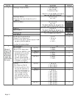
Program 0319 - VoIP Operating Mode
The VoIPU PCB work in NT mode. Following program assigns a slot number and operating mode for each VoIP PCB
index (1 –5).
If the VoIPU PCB is working, changing this option will cause the PCB to reset.
VOIPU index number (1 – 5)
Cabinet Number 1, Slot Number Options: 4-8 or 0 (No PCB)
Cabinet Number 2, Slot Number Options: 12-16 or 0 (No PCB)
Cabinet Number 3, Slot Number Options: 20-24 or 0 (No PCB)
Mode: 1:
●
NT mode - trunks = 1
●
TE mode - terminals = 2
(Not Currently Supported)
When the VoIP PCB is installed, the system will assign 4 trunk ports per VoIP PCB. If there is no slot number in Program
0319, no port numbers will be assigned. Ports are assigned in the order the PCB is installed. Port assignment and the VoIP
Index number are independent of each other.
➻
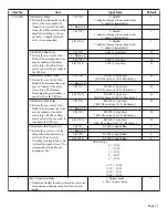
Program 0501 - System Numbering
If using F-Routing, define the digit(s) to be used to initiate Flexible Routing (9).
➻
Program 0603 - Entering Abbreviated Dialing Numbers and Names
When using ARS to route calls, enter the digits that will be dialed to reach the destination IP address. These entries must
be made in the range specified in Program 0605.
➻
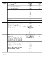
Program 0604 - Common Abbreviated Dialing Trunk Group
Enter the VoIP trunk group number (01 to 26) for the table number in Program 0928.
➻
Program 0605 - Abbreviated Dial Table Area for IP Address
To determine the trunk group, the software can search dialed digits in the Abbreviated Dialing Number table. If you want
to use this feature, program the range setting below.
Entries:
Start Address: 0 – 1999
Length: 0 – 2000
Default:
Start Address: 0
Length: 0
➻
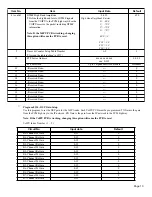
Program 0901 - Basic Trunk Port Setup (Part A), Item 3: CODEC Gain Type
VoIP trunks will ignore the setting in this program and will use the settings in
Program 0154 - DSP Gain Setup
instead.
Refer to
Program 0901:23
for information on conference call gain settings.
➻
Program 0901 - Basic Trunk Port Setup (Part A), Items 14-17, 32-35: Trunk Service Type
For each VoIP trunk, set this option to
’
3
’
(DID trunk) or ‘5’ (tie line). Use the i-Series Software Manual, P/N
92000SWG**), to complete all the required DID or tie line programming.
Input Data
Default
Item 1: Gatekeeper Mode for VoIP Trunk
0: Overlap Sending
1: En Bloc Sending
0
Item 2: Reserved
0
Item 3: Reserved
0
Item 4: Reserved
0
Item 5: Reserved
0
Item 6: Reserved
0
Item 7: Reserved
0
Item 8: Reserved
0

