Page 14
➻
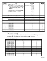
Program 0155 - VoIP Timer and Count Setup
Program the timer and count value for the VoIP timers. There are three available tables, all using the same entries from the
table below. The default settings for each of the tables is the same. These entries do not normally need to be changed from
their default setting. These tables are assigned to a VoIP PCB in Program 0153: Item 9, Timer and Counter Setup Table
Number.
Note: If the VoIPU PCB is working, changing this option will cause the PCB to reset.
B8-Channel Tx Gain
0-29
0
B8-Channel Rx Gain
0-29
0
Entry Values for Above:
0 = 0, 1 = +1.0, 2 = +2.0, 14 = +14.0, 15 = 0, 16 = -1.0, 17 = -2.0, etc.)
Item No.
Item
Input data
Default
1
T101
1-254 seconds
5
2
T102
1-254 seconds
50
3
T103
1-254 seconds
50
4
T105
1-254 seconds
50
5
T106
1-254 seconds
5
6
T108
1-254 seconds
50
7
T109
1-254 seconds
50
8
T301
180-254 seconds
180
9
T302
1-254 seconds
15
10
T303
1-254 seconds
4
11
T304
1-254 seconds
15
12
T310
1-254 seconds
10
13
N100
1-254
2
14
Round trip delay timer
0-65535 seconds
0
15
GRQ timer
1-254 seconds
5
16
GRQ count
1-254
2
17
RRQ timer
1-254 seconds
3
18
RRQ count
1-254
2
19
URQ timer
1-254 seconds
3
20
URQ count
1-254
1
21
ARQ timer
1-254 seconds
3
22
ARQ count
1-254
2
23
BRQ timer
1-254 seconds
3
24
BRQ count
1-254
2
25
IRQ timer
1-254 seconds
3
26
IRQ count
1-254
1
27
IRR timer
1-254 seconds
5
28
IRR count
1-254
2
29
DRQ timer
1-254 seconds
3
30
DRQ count
1-254
2
31
LRQ timer
1-254 seconds
3
32
LRQ count
1-254
2
33
RAI timer
1-254 seconds
3
34
RAI count
1-254
2
Circuit No
Input data
Default

