Page 12
6
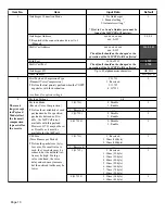
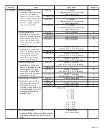
Echo Canceller Mode
1: Enable
2: Disable
1
Echo Canceller Tail size (Delay Volume)
1: 8ms
2: 16ms
2
Echo Canceller Nonlinear Processor
1: Enable
2: Disable
1
Echo Canceller NLP Comfort Noise Level
0-30
Entries:
0 = -70
1 = -69
2 = -68
3 = -67
|
28 = -42
29 = -41
30 = -40
0
Echo Canceller NLP Comfort Noise
Configuration
0: Adaptive
1: fixed
0
Echo Canceller 4 Wire-Detect
0: Disable
1: Enable
1
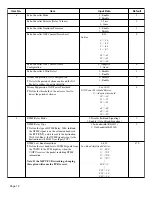
7
Silence Suppression VAD Configuration
¥ Detects the period of silence and send the Nil
Packet to reduce the network traffic.
0: Disable
1: Enable
0
Silence Suppression VAD Power Threshold
¥ Define the threshold of the nil voice level to
detect the period of silence.
0 or 20-50
VAD Power Threshold Entries:
0 = Adaptive threshold
20 = -20
21 = -21
22 = -22
|
48 = -48
49 = -49
50 = -50
0
8
DTMF Relay Mode
0: Disable (In-Band Signaling)
1: Enable (Out-of-Band Signaling)
1
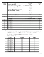
DTMF Relay Type
¥ Define the type of DTMF Relay. With In-Band ,
the DTMF signal is on the extension header of
the RTP (UDP), and it is sent to the destination.
With Out-Band , the DTMF signal is sent to the
destination with H.245 User Input (TCP).
1: In-bandwidth (Rfc2833)
2: Out-bandwidth (H.245)
2
DTMF Low Band Amplitude
¥ Define the low band level of DTMF signals from
the VOIPU to the PCM highway when the
VOIPU receives the packet including DTMF
information.
Note: If the VoIPU PCB is working, changing
this option will cause the PCB to reset.
0-830
Low Band Amplitude Entries:
0 = -80.0
1 = -79.9
2 = -79.8
3 = -79.7
|
800 = 0
|
828 = 2.8
829 = 2.9
830 = 3.0
670
Item No.
Item
Input Data
Default

