


30
30
gage) and when you have a steady echo, press the ENTER key. This sets the probe Zero
and any offset between the probe and surface under inspection.
8.
Place the probe on the 0.500"(or thicker) Step of the step block
9.
Select VEL on the Keypad, then use the Up & Dn arrow keys to adjust the Velocity. It
should range between 0.2320 to 0.2350 in general terms for un-coated steel.
10.
Check the thickness in between and they should be very close. If you would like the
values closer you can continue by placing the probe on the Low Step and use the
ZERO/LoCAL to set the low thickness closer then move the probe to the thicker
section and press the VEL/HiCAL Key and adjust the thickness to read the thick step.
Repeat until satisfied. Under most conditions you should not have to go through the
extra steps.
11.
Once calibrated press the B-SCAN Key.
12.
Cursor to TYPE and use the Up & Dn arrows to select T-SCAN. This will provide a
Cross Section view of the area being inspected.
13.
Move the Cursor to Select POS on the Menu.
14.
Use the Up & Dn arrows to select ENCODED L-R or any other desired plotted motion.
15.
Place the cart on a surface to be inspected and the pointer above
the B-SCAN graphic screen should move with the movement of
the scanner.
16.
Adjust the SCALE as desired to either speed up the motion (less
distance information) on the screen or slow down the motion
(more info on screen).
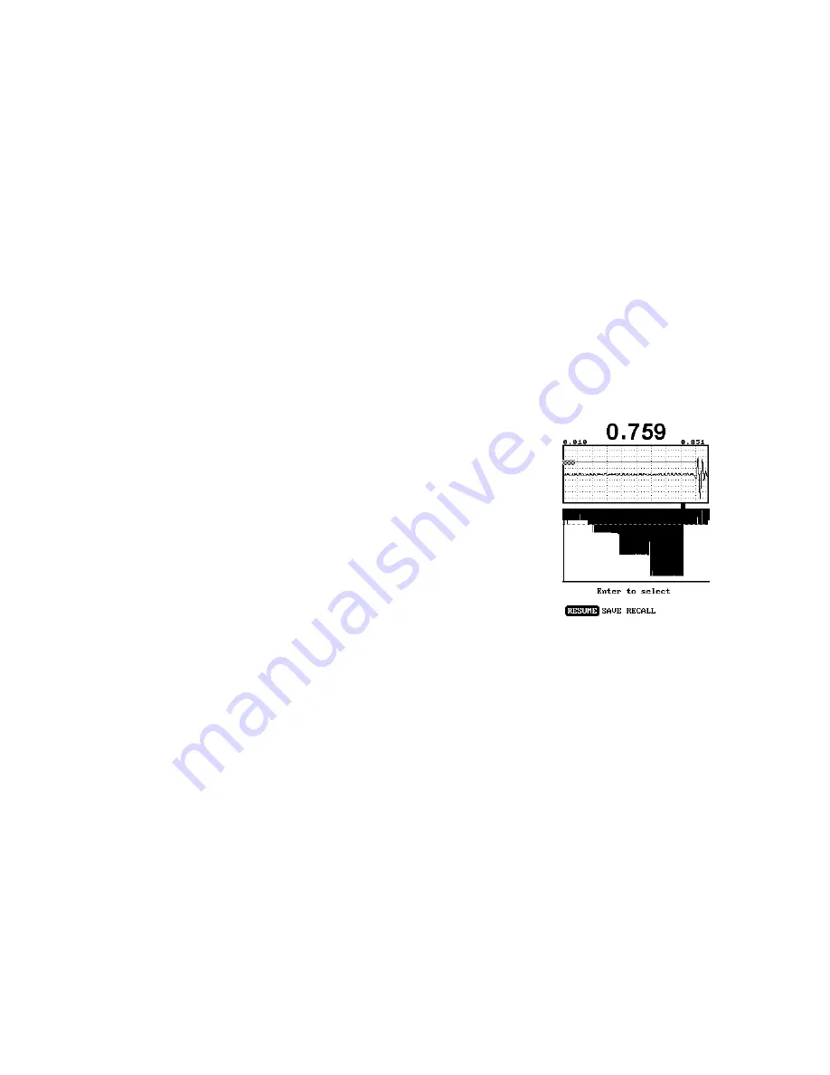
17.
Finally, re-check your gain for the material you re testing to be
sure you are receiving good echo height to trigger the gage. If
the gain is too low, there will be dropout (white or blank areas)
on the B-SCAN. If the B-Scan shows the same number all the
time be sure the gage is not continuously triggered on surface
noise of some sort.


