background image

Display User Interface | 9

DVI-1 Output

To change Redrive or Screen settings, tap the 

 button, which toggles selection between the two settings.

Redrive

: Outputs DVI-1 signal input to DVI-1 RE-DRIVE (Output) connector.

Screen

: Outputs display image, including PIP and OSD, to the DVI-1 RE-DRIVE (Output) connector.

Keypad Color

To modify the Keypad color setting, tap the 

 or 

 buttons.

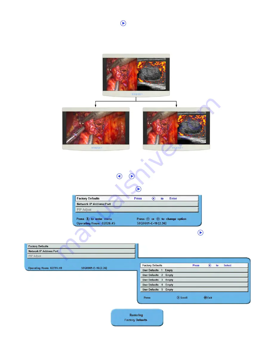
Factory Defaults

To return all settings to factory preset values, tap the 

 button to open the Factory Defaults menu.

Next, tap the 

SCROLL

 button to select the Factory Defaults function, and tap the 

 button. The “Restoring

Factory Defaults” message displays while processing.

Display Image

DVI-1 + VGA

Redrive

DVI-1 to DVI-1 Output

Screen

DVI-1 + VGA to DVI-1 Output

Содержание Radiance Ultra SERIES

Страница 1: ...Radiance Ultra with optional ZeroWire Embedded Wireless Technology USER MANUAL ENGLISH ...

Страница 2: ......

Страница 3: ...without notice NDSsi provides this information as reference only Reference to products from other vendors does not imply any recommendation or endorsement This document contains proprietary information protected by copyright No part of this manual may be reproduced by any mechanical electronic or other means in any form without prior written permission of NDSsi All trademarks are the property of t...

Страница 4: ......

Страница 5: ...s 4 Picture Menu 5 Picture Menu Parameters 5 Color Menu 7 Setup Menu 8 Picture In Picture Controls 12 PIP Secondary Image Size Control 12 SWAP Exchange Primary and Secondary Inputs 12 General Purpose Input Output 13 Image Adjustment 13 Enclosure Assembly and Cleaning 15 Cable Cover Installation 15 Cleaning Instructions 15 Connector Panels Overview 17 Radiance Ultra Product Configurations 17 Radian...

Страница 6: ... 27 Channel Usage 27 Multi System Installation 27 Performance 27 ZeroWire Transmitter Setup 28 ZeroWire G2 Transmitter Wiring 28 ZeroWire G2 Transmitter Connector Panel 28 ZeroWire G2 Transmitter Y Adapter Cables 28 ZeroWire G2 Transmitter Power Supplies 29 Positioning and Orientation 29 ZeroWire Quick Start Linking 30 Wireless Linking Status Messages 31 Troubleshooting 33 Display Troubleshooting ...

Страница 7: ...lowed This equipment system is intended for use by healthcare professionals only This product is intended for continuous operation Safety Compliance This product is T U V approved with respect to electric shock fire and mechanical hazards only in accordance with CAN CSA C22 2 No 60601 1 and ANSI AAMI ES60601 1 Safety Compliance This device meets the requirements of EN60601 1 so as to conform to th...

Страница 8: ...dications 1 Do not use this product in the presence of flammable anesthetics mixture with air oxygen or nitrous oxide 2 No part of this product may come in contact with a patient Never touch the product and a patient at the same time 3 This product is capable of displaying Radiology PACS images for reference not diagnostic purposes only 4 For mission critical applications we strongly recommend tha...

Страница 9: ...nician for help Accessory equipment connected to this product must be certified according to the respective IEC Standards i e IEC 60950 1 for data processing equipment and IEC 60601 1 for medical equipment Furthermore all configurations shall comply with the system standard IEC 60601 1 1 Anyone who connects additional equipment to the signal input part or signal output part configures a medical sy...

Страница 10: ...rchase sale lease rental installation or use of such NDS products these terms and conditions or with respect to any the terms of any agreement which incorporates these terms and conditions SOME JURISDICTIONS DO NOT ALLOW EXCLUSIONS AND DISCLAIMERS OF CERTAIN WARRANTIES OR LIMITATIONS OF LIABILITY SO THE LIMITATIONS AND OR EXCLUSIONS SET FORTH HEREIN MAY NOT APPLY IN THAT EVENT LIABILITY WILL BE LI...

Страница 11: ...LECT Primary Input Selection To display the QUICK SELECT menu tap the INPUT button The QUICK SELECT menu allows the user to select any active input as Primary with a single tap on the Keypad button under the QUICK SELECT icon labeled with the target input QUICK SELECT icons designating active inputs are tinted light blue QUICK SELECT options apply only to selection of a Primary input If an input s...

Страница 12: ...or to make it the Secondary input tap the button A Secondary input can be cleared by positioning the selection cell on the row of the input and tapping the button Inputs marked with an X in the Secondary column are unavailable for designation as a Secondary input The Input menu will automatically close 30 seconds after the last action It can also be closed by tapping the INPUT button The following...

Страница 13: ...u automatically closes 30 seconds after the last action It can also be closed by pressing the MENU button Note Grayed out descriptions indicate parameters not available for the current signal or input configuration ZeroWire Menu Note The ZeroWire Menu is enabled only on displays configured with an embedded ZeroWire Receiver To enter the menu and activate the ZeroWire linking process tap the SCROLL...

Страница 14: ...ogressive stages in the linking process When linking is complete the Transmitter display image will appear on the Receiver display For an alternative ZeroWire linking procedure see ZeroWire Quick Start Linking on page 30 ZeroWire Receiver Status Messages ZeroWire status messages indicate stages of the linking process Refer to Wireless Linking Status Messages on page 31 for complete descriptions of...

Страница 15: ...r enabled when the input is 16 9 480P 576P or interlaced Tap the or buttons to select 0 The image is displayed at a size that fills the screen without losing any video information Image could be displayed as letterboxed with black bars top and bottom or left and right 1 2 3 4 5 or 6 Incrementally enlarges and crops the centered image As the image becomes larger video information is lost on all sid...

Страница 16: ...nc To enable SmartSync tap the button Alternative Modes To make an Alternative Modes adjustment tap the button After selecting Alternative Modes the mode changes incrementally each time the button is tapped until the selected mode equals the maximum available The next tap of the button restores the initial mode Flip Rotate Tap the or buttons to select one of 5 options Fine Tune Currently not avail...

Страница 17: ...he or buttons Brightness To adjust brightness tap the or buttons Brightness is also controlled by the Brightness Contrast button described on page 13 Contrast To adjust contrast tap the or buttons Contrast is also controlled by the Brightness Contrast button described on page 13 Video Level To adjust signal range tap the or buttons Normal Provides a dynamic range equivalent to the incoming signal ...

Страница 18: ...ignal is restored its image is displayed again and the Secondary image is placed behind the Primary image If both the Primary and Secondary signals are lost the monitor alternately scans the Primary and Secondary inputs until a signal is detected on one of them When a signal is detected on the Primary or Secondary input its image is displayed on the monitor Menu Lock To enable Menu Lock press the ...

Страница 19: ...D to the DVI 1 RE DRIVE Output connector Keypad Color To modify the Keypad color setting tap the or buttons Factory Defaults To return all settings to factory preset values tap the button to open the Factory Defaults menu Next tap the SCROLL button to select the Factory Defaults function and tap the button The Restoring Factory Defaults message displays while processing Display Image DVI 1 VGA Red...

Страница 20: ...The Restoring User Profile message displays while processing To clear a User Defaults profile select the saved User Defaults profile and tap the Brightness Contrast button The Clearing User Profile message displays while processing Network IP Address Port This parameter allows the user to configure the device with static or dynamic IP settings and to configure the Ethernet port for control the dis...

Страница 21: ...gits Tap the or buttons to configure the first octet then tap the SCROLL button to highlight and set each subsequent octet until all four are set correctly Consult your IT administrator if you do not know the settings for the network you are connecting to Subnet Mask The Subnet Mask must be set manually when DHCP is disabled To set the Subnet Mask tap the button to enter edit mode and highlight th...

Страница 22: ... with Primary image displayed full screen Split Screen Primary and Secondary images are displayed on equal screen halves with above below letterboxing Split Screen Overscan Primary and Secondary images are displayed on equal screen halves with image height maximized and left right cropping Full Screen Primary Primary image displayed full screen with Secondary image hidden SWAP Exchange Primary and...

Страница 23: ... twice to access the Contrast control or tap it three times to access the Backlight control Tap the or buttons to adjust the controls Brightness Control To adjust brightness of the Primary input tap the or buttons If a Secondary input is enabled tap the Brightness Contrast button again to access the Secondary brightness control NOTE Setting brightness too high or too low reduces the range of shado...

Страница 24: ...14 Display User Interface ...

Страница 25: ...able cover in the upper left and right corners Cleaning Instructions Caution Prior to cleaning units should be turned OFF and disconnected from respective power sources Do not allow liquids to enter the interior of the unit as severe damage to the unit can result Do not use solvents such as benzene or thinner or any acid alkaline or abrasive detergents Thoroughly wipe all the front glass and plast...

Страница 26: ...16 Enclosure Assembly and Cleaning ...

Страница 27: ... and 3G SDI 2 RE DRIVE outputs are active only with display powered on 3 ND OS connector is designated for installing firmware upgrades The ND OS connector can also be used for display control See Communication Port on page 8 Inputs Connector Types Outputs Connector Types DVI 1 DVI I 1920 x 1200 max DVI 1 DVI I SDI 1 SDI 2 BNC RGBS 1 YPbPr 1 VGA 1 SOG 1 DVI I RGBS 1 YPbPr 1 VGA 1 SOG 1 DVI I DVI 2...

Страница 28: ...ER 24 T M D S CLOCK 5 T M D S DATA 4 15 GND DVI I IN Only 6 DDC CLOCK 16 HOT PLUG DETECT C1 ANALOG RED 7 DDC DATA 17 T M D S DATA 0 C2 ANALOG GREEN 8 ANALOG VERTICAL SYNC DVI I IN Only 18 T M D S DATA 0 C3 ANALOG BLUE 9 T M D S DATA 1 19 T M D S DATA 0 5 SHIELD C4 ANALOGHORIZONTALSYNC 10 T M D S DATA 1 20 T M D S DATA 5 C5 ANALOG GROUND Pin Description Pin Description Pin Description 1 RED 6 GND R...

Страница 29: ... 35Z0047 is available from NDS Pin Signal Description 1 TX No Connection 2 TX Transmit Return 3 RX Receive 4 N C No Connection 5 N C No Connection 6 RX Receive Return 7 N C No Connection 8 N C No Connection Pin Name Description 1 VCC 5 VDC 2 D Data Transmit Return 3 D Data Transmit 4 GND Ground 1 8 1 4 ...

Страница 30: ...e The size of Secondary image increases each time the PIP Size is connected to GND See page 12 for details Record Indicator The Record Indicator is displayed while a contact closure to the GND is present the indicator is removed when the contact is opened The Record Indicator is displayed in the monitor s top left corner Pin Name Description 1 N C No Connection 2 N C No Connection 3 N C No Connect...

Страница 31: ...Open Off Switch This symbol appears on the open or off side of the display On Off switch Cable Bend Radius We recommend that the bend radius of metallic cables be no less than 63 mm 2 5 inches or 7 times the diameter of the cable whichever is greater The bend radius of Fiber Optic cables should be no less than 10 times the diameter of the cable Sharper bends can damage the cable and or degrade the...

Страница 32: ...22 Connector Panels Overview ...

Страница 33: ... 0 7 V p p 0 7 V p p 0 7 V p p RGBS Input Signal Level 0 7 V p p 0 7 V p p 0 7 V p p RGBS Input Sync Level 0 4 4 0 V p p 0 4 4 0 V p p 0 4 4 0 V p p DC Input 24 V 6 25 A 24 V 6 25 A 24 V 6 25 A DC Power Consumption Nominal b 70 W 52 W 87 W AC Power Consumption Nominal b 81 W 60 W 98 W Dimensions W x H x D 26 7 x 17 5 x 3 3 in 678 x 445 x 84 mm 30 7 x 20 1 x 3 4 in 780 x 511 x 86 mm 30 7 x 20 1 x 3...

Страница 34: ...ertical Frequency Hz Horizontal Resolution pixels Vertical Resolution lines Vertical Frequency Hz 720 480i 29 97 1280 720p 59 94 720 483i 29 97 1920 1080sF 24 720 487i 29 97 1920 1080p 24 720 576i 25 1920 1080p 25 720 587i 25 1920 1080p 29 97 1280 720p 24 1920 1080i 25 1280 720p 25 1920 1080i 29 97 1280 720p 30 1920 1080p 50 1280 720p 50 1920 1080p 59 94 Horizontal Resolution pixels Vertical Resol...

Страница 35: ...05A SIISK63102 6705A SIISK63101 The ZeroWire Transmitter complies to the above standards only when used with the supplied medical grade power supply Intended Use and Contraindications Intended Use The Radiance Ultra series ZeroWire Embedded and ZeroWire G2 is a paired wireless video communication transmitter and receiver intended for delivery of video signals from a source such as an endoscopy cam...

Страница 36: ...or the ZeroWire to be operating without any interference with each other At any time if the ZeroWire is believed to be causing or getting the interference from those devices simply move the devices away from each other and then maintain at least the separations as specified in the table Wireless Signal Type 60 GHz Wireless HD band WiHD Frequency Band 57 64 GHz Video Compression None Video Inputs T...

Страница 37: ... the room 3 Groups of two ZeroWire systems may be set in multiple rooms providing the rooms are spaced at least 25 feet 7 6 m apart 4 ZeroWire G2 Transmitters and Receivers should not be installed in metal cabinets or surrounded by metallic objects as this will prevent Transmitter communication with the Receiver Multi System Installation When two paired Transmitter and Receiver systems are to be i...

Страница 38: ...dapter cable for powering the ZeroWire unit Two types of Y adapter cables are available Where applicable the appropriate Y cable is included in the display accessory kit SwitchCraft Y Adapter Cable 35X0096 24 VDC Cable DVI Cable 3G SDI Cable optional SDI Output DVI Output Power to Transmitter Power to Display Transmitter DVI Video Source Power Connector DVI Input 3G SDI Input USB Port Used for Tra...

Страница 39: ...tor with mounted ZeroWire Transmitter and the Secondary Monitor with embedded ZeroWire Receiver at a distance of 8 feet 2 4 meters and confirm that both displays are aligned vertically and horizontally within 10 at heights of 5 feet 1 5 meters as shown below GlobTek GTM91120 3024 T3A Ault MW172KB2400B02 J3 of the Y adapter or 24 VDC power supply cable connects here Supported 24 VDC power supply mo...

Страница 40: ...once again to access the ZeroWire Link Menu 5 Press and hold the INPUT button for three seconds until the progress bar fills the box 6 At the display mounted ZeroWire Transmitter press and hold the button until the blue Linking LED begins flashing After the Transmitter and Receiver units identify each other and begin linking both the Linking and Status LEDs will flash rapidly for several seconds 7...

Страница 41: ...ed system the typical sequence of status messages presented on the Receiver display begins with Searching for Transmitter Stage 1 Searching for Transmitter If not activated already activate on ZeroWire Transmitter Stage 2 Establishing Link Stage 3 Wireless Linked Stage 1 Searching for Transmitter Stage 2 Establishing Link Searching for Transmitter If not activated already activate on ZeroWire Tran...

Страница 42: ...mitter Found status message will be presented on the Receiver display For suggestions on how to solve linking problems see ZeroWire Troubleshooting on page 34 Stage 3 Wireless Linked Stage 1 Searching for Transmitter Stage 2 No Transmitter Found Wireless Linked Searching for Transmitter No Transmitter Found ...

Страница 43: ...in grays and light colors Adjust the Frequency until the image just fits the screen Horizontal position adjustment can be used to verify that Frequency is set correctly Line up the image on the left edge of the screen and then shift by one click to the right The image should have one column off the screen on the right side if the Frequency is set correctly Testing and Adjusting Frequency VGA RGBS ...

Страница 44: ...d Verify the Transmitter unit is ON or Source signal is connected No image on display after changing input resolution Cycle both ZeroWire Transmitter s and Receiver s power Poor or Intermittent Video Transmitter and Receiver are spaced more than 30 feet 9 1 m apart See Positioning and Orientation on page 29 DVI or SDI Transmitter only connections Confirm that the cables are properly connected Cros...

Страница 45: ...he Receiver During installation the ZeroWire link video quality should be tested with the Transmitter and Receiver at different orientation angles acceptable orientation angles are shown on page 10 Non line of sight operation is discussed under Performance on page 27 We recommend that the system be thoroughly tested prior to using it in any surgical procedures Do not use power supplies or cable ac...

Страница 46: ...tatic discharge ESD IEC 61000 4 2 6 kV contact 8 kV air 6 kV contact 8 kV air The product uses RF energy only for its internal function Therefore its RF emissions are very low and are not likely to cause any interference in nearby electronic equipment Electrical fast transient burst IEC 61000 4 4 2 kV for power supply lines 2 kV for power supply lines The product is suitable for use in all establi...

Страница 47: ...mitters as determined by an electromagnetic site surveya should be less than the compliance level in each frequency rangeb Interference may occur in the vicinity of equipment marked with the following symbol NOTE 1 At 80 MHz and 800 MHz the higher frequency range applies NOTE 2 These guidelines may not apply in all situations Electromagnetic propagation is affected by absorption and reflection fro...

Страница 48: ...um output power W of transmitter Separation distance in meters according to frequency of transmitter 150 kHz to 80 MHz 80 MHz to 800 MHz 800 MHz to 2 5 GHz 0 01 0 12 0 12 0 23 0 1 0 38 0 38 0 73 1 1 2 1 2 2 3 10 3 8 3 8 7 3 100 12 12 23 For transmitters rated at a maximum output power not listed above the recommended separation distance d in meters m can be estimated using the equation applicable ...

Страница 49: ......

Страница 50: ... CA 95138 USA 408 776 0085 info ndssi com Europe GSI Distribution USD GmbH Münchner Strasse 2A 82152 Planegg Germany 49 89 31 707 100 info gsig europe gsig com Asia Pacific East Square Omori 6 20 14 Minamioi Shinagawa ku Tokyo 140 0013 Japan 81 3 5753 2466 info ndssi jp Contact ...

Отзывы: