background image

Display User Interface | 3

Display User Interface

Display Keypad

The Display Keypad is centered on the lower front surface of the display enclosure, providing controls for
adjustment of display parameters using the On Screen Display (OSD) Menu system.

Menu Navigation

INPUT and MENU Buttons: Open OSD Menus

To open the Input Menu, press the 

INPUT

 button. To open the Display Menu, press the 

MENU

 button.

SCROLL Button: Vertical Selection Control

To enter a menu and begin a parameter selection process, press the 

SCROLL

 button. The top parameter

row is first selected, and the selection moves downward to the next row with each successive press of the
button.
To exit a menu, use the 

SCROLL

 button to move the selection to the bottom menu row, and then press the

SCROLL


button just once to highlight the menu tab, where you can use the 

 or 

 buttons to select another

menu tab.

Left/Right Buttons: Horizontal Selection Controls

To adjust a parameter, select the parameter row using the 

SCROLL

 button, then press the 

 or 

buttons to make the adjustment or to select a setting.

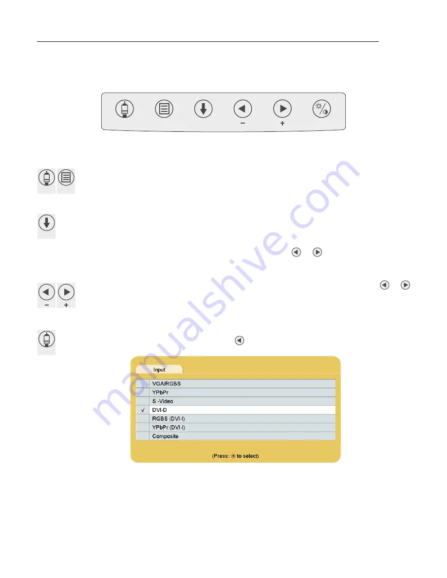
Input Menu

To select or change an input source, press the 

INPUT

 button to access the Input Menu. press the 

SCROLL

button to highlight the desired input and press the 

 button to select it. A 

 symbol in the left column

designates the active input.

The Input Menu automatically closes 30 seconds after the last action. It can also be closed by pressing the 

INPUT

button.

INPUT

MENU

SCROLL

INPUT

MENU

SCROLL

INPUT

Содержание EndoVue 19"

Страница 1: ...EndoVue USER MANUAL ENGLISH ...

Страница 2: ......

Страница 3: ...without notice NDSsi provides this information as reference only Reference to products from other vendors does not imply any recommendation or endorsement This document contains proprietary information protected by copyright No part of this manual may be reproduced by any mechanical electronic or other means in any form without prior written permission of NDSsi All trademarks are the property of t...

Страница 4: ......

Страница 5: ...nu Navigation 3 INPUT and MENU Buttons Open OSD Menus 3 SCROLL Button Vertical Selection Control 3 Left Right Buttons Horizontal Selection Controls 3 Input Menu 3 Display Menu 4 Picture Menu 4 Color Menu 5 Setup Menu 5 Defaults Menu 6 Image Adjustment 6 Connector Panel Overview 7 EndoVue Connector Panel 7 Connector Types 7 Data Connectors and Pinouts 7 DVI I Digital and Analog 7 VGA 8 S Video 8 Co...

Страница 6: ...ii Table of Contents Electromagnetic Compatibility Tables 15 Electromagnetic Emissions 16 Electromagnetic Immunity 16 Recommended Separation Distances 17 Contact 20 ...

Страница 7: ... incoming signals of various signal types to match the resolution of the LCD panel The user can make adjustments to video parameters using the front keypad of the monitor with the On Screen Display OSD interface to optimize the viewing experience for different applications To prevent fire or shock hazards do not expose this unit to rain or moisture Also do not use this unit s polarized plug with a...

Страница 8: ...t complies with the hospital local and national impedance requirements A ground post is located on the back of the product to use for grounding the chassis of the unit Any such ground must be installed in accordance with applicable electrical codes The ground post location is shown in the EndoVue Connector Panel diagram on page 7 Grounding reliability can only be achieved when the equipment is con...

Страница 9: ...d a system and is therefore responsible for the system to comply with the requirements of IEC or ISO safety standards If in doubt speak with a qualified technician If such equipment and other medical devices are connected to form a medical electrical system s a green light indicator shall be provided on the final ME system s to indicate that this equipment is ready for normal use Image Retention N...

Страница 10: ...to the respective IEC Standards i e IEC 60950 1 for data processing equipment and IEC 60601 1 for medical equipment Furthermore all configurations shall comply with the system standard IEC 60601 1 1 Anyone who connects additional equipment to the signal input part or signal output part configures a medical system and is therefore responsible that the system complies with the requirements of system...

Страница 11: ...epair and Return requires the defective unit to be returned to our service location for repair 2 Cost of shipment of the defective unit to NDS is the responsibility of the customer Cost of shipment of the repaired unit to Customer is the responsibility of NDS 3 NDS reserves the right in its sole discretion to provide Customer with a comparable refurbished replacement unit in lieu of repair of cust...

Страница 12: ...r enforcement efforts customer shall be liable for all costs thereof including attorney s fees NDS reserves the right to suspend warranty coverage to any customer who is in default of payment until such payment has been made DISCLAIMER This limited product warranty sets forth your sole and exclusive remedy and NDS s sole and exclusive liability under the Standard Limited Warranty described herein ...

Страница 13: ...g screw holes of the stand mounting bracket over the four hole attachment interface on the monitor back Insert one of the four provided cap screws into a screw hole and lightly tighten Repeat the process with the remaining screws and then check to confirm that the mounting bracket is flat against the back surface of the monitor before tightening all screws securely Note Mounting bracket of the sta...

Страница 14: ...d OFF and disconnected from the power source Do not allow liquids to enter the interior of the unit as severe damage to the unit can result Do not use solvents such as benzene or thinner or any acid alkaline or abrasive detergents Front Glass Thoroughly wipe the front glass surface with a lint free cloth For persistent spots or smudges use a lint free cloth dampened with distilled water Do not use...

Страница 15: ... press of the button To exit a menu use the SCROLL button to move the selection to the bottom menu row and then press the SCROLL button just once to highlight the menu tab where you can use the or buttons to select another menu tab Left Right Buttons Horizontal Selection Controls To adjust a parameter select the parameter row using the SCROLL button then press the or buttons to make the adjustment...

Страница 16: ...Video Parameter enabled when the input is 16 9 480P 576P or interlaced Press the or buttons to select 0 The image is displayed at a size that fills the screen without losing any video information Image could be displayed as letterboxed with black bars top and bottom or left and right 1 2 3 4 5 or 6 Incrementally enlarges and crops the centered image As the image becomes larger video information is...

Страница 17: ...t of the image press the or buttons Setup Menu Menu Position To select from nine preset screen locations for display of the OSD menus press the or buttons Language To select one of 18 languages Chinese Danish Dutch English Finnish French German Greek Italian Japanese Korean Norwegian Polish Portuguese Russian Spanish Swedish and Turkish press the or buttons DPMS Enable To enable or disable Display...

Страница 18: ...s profile select the saved User Defaults profile and press the Brightness Contrast button The Clearing User Profile message displays while processing Image Adjustment Brightness Contrast Button Press the Brightness Contrast button once to access the Brightness control Press the button twice to access the Contrast control or press it three times to access the Backlight control Press the or buttons ...

Страница 19: ... Ohm differential Analog 75 Ohm terminated VGA RGBS YPbPr HD 15 75 Ohm terminated Composite BNC 75 Ohm terminated S Video DIN 4 75 Ohm terminated Pin Signal Pin Signal Pin Signal 1 T M D S DATA 2 11 T M D S DATA 1 3 SHIELD 21 N C 2 T M D S DATA 2 12 N C 22 T M D S CLOCK SHIELD 3 T M D S DATA 2 4 SHIELD 13 N C 23 T M D S CLOCK 4 N C 14 5V POWER 24 T M D S CLOCK 5 N C 15 GND DVI I IN Only 6 DDC CLOC...

Страница 20: ...escription 1 RED 6 GND RED 11 N C 2 GREEN 7 GND GREEN 12 DDC_SDA 3 BLUE 8 GND BLUE 13 HORIZ SYNC 4 N C 9 5VD 14 VERT SYNC 5 GND 10 SYNC GND 15 DDC_SCL Pin Name Description 1 GND Ground Y 2 GND Ground Y 3 Y Intensity Luminance 4 C Intensity Chrominance Pin Name Description 1 DATA Pin 2 GROUND Sleeve Pin Name Description 1 Vcc 5 VDC 2 D Minus Data Return 3 D Plus Data Transmit 4 ID 5 GND Ground 1 5 ...

Страница 21: ...Power Cable P N 35X0100 contact North America and Asia Pacific customercare ndssi com Europe customercare emea ndssi com Cable Bend Radius We recommend that the bend radius of metallic cables be no less than 63 mm 2 5 inches or 7 times the diameter of the cable whichever is greater The bend radius of Fiber Optic cables should be no less than 10 times the diameter of the cable Sharper bends can dam...

Страница 22: ...10 Connector Panel Overview ...

Страница 23: ...2 80 in 566 x 408 x 71 mm 29 7 x 19 1 x 3 86 in 753 x 485 x 98 mm Display Weightb 10 8 lb 4 9 kg 12 5 lb 5 7 kg 14 8 lb 6 7 kg 19 4 lb 8 8kg Operating Temperature 32 95 F 0 35 C 32 95 F 0 35 C 32 95 F 0 35 C 32 95 F 0 35 C Storage Temperature 4 122 F 20 50 C 4 122 F 20 50 C 4 122 F 20 50 C 4 122 F 20 50 C Transport Temperature 4 122 F 20 50 C 4 122 F 20 50 C 4 122 F 20 50 C 4 122 F 20 50 C Operati...

Страница 24: ...4 70 01 1440 900 59 94 720 400 85 04 1152 864 75 1600 1200i 48 04 720 480i 29 97 1152 864 85 1600 1200 60 720 480p 59 94 1152 900 66 1920 1080p 24 720 576i 25 1280 720p 24 1920 1080p 25 720 576p 50 1280 720p 25 1920 1080p 29 97 800 600 56 25 1280 720p 30 1920 1080i 25 800 600 60 32 1280 720p 50 1920 1080i 29 97 800 600 60 38 1280 720p 59 94 1920 1080p 50 800 600 72 19 1280 960i 29 97 1920 1080p 59...

Страница 25: ... grays and light colors Adjust the Frequency until the image just fits the screen Horizontal position adjustment can be used to verify that Frequency is set correctly Line up the image on the left edge of the screen and then shift by one click to the right The image should have one column off the screen on the right side if the Frequency is set correctly Testing and Adjusting Frequency VGA RGBS YP...

Страница 26: ...14 Troubleshooting ...

Страница 27: ...MC guideline information provided in this manual and verification of all medical devices in simultaneous operation are required to ensure the electromagnetic compatibility and co existence of all other medical devices prior to a surgical procedure The following EMC tables are provided for your reference Electromagnetic Emissions on page 16 Electromagnetic Immunity on page 16 Recommended Separation...

Страница 28: ...tatic discharge ESD IEC 61000 4 2 6 kV contact 8 kV air 6 kV contact 8 kV air The product uses RF energy only for its internal function Therefore its RF emissions are very low and are not likely to cause any interference in nearby electronic equipment Electrical fast transient burst IEC 61000 4 4 2 kV for power supply lines 2 kV for power supply lines The product is suitable for use in all establi...

Страница 29: ...cy To assess the electromagnetic environment due to fixed RF transmitters an electromagnetic site survey should be considered If the measured field strength in the location in which the product is used exceeds the applicable RF compliance level above the product should be observed to verify normal operation If abnormal performance is observed additional measures may be necessary such as re orienti...

Страница 30: ...18 Electromagnetic Compatibility Tables ...

Страница 31: ......

Страница 32: ...many 49 89 31 707 100 info novanta europe novanta com Asia Pacific Novanta Japan East Square Omori 6 20 14 Minamioi Shinagawa ku Tokyo 140 0013 Japan 81 3 5753 2466 info ndssi jp Oriental Media Center Suite 2302 Tower C No 4 Guang Hua Road Chao Yang District Beijing 100026 China 86 10 8559 7859 info ndssi com cn NDS Quality System ISO 9001 2008 and ISO 13485 2003 FDA Registration 2954921 ...

Отзывы: