background image


Chapter 2:  Hardware Installation  2-11 

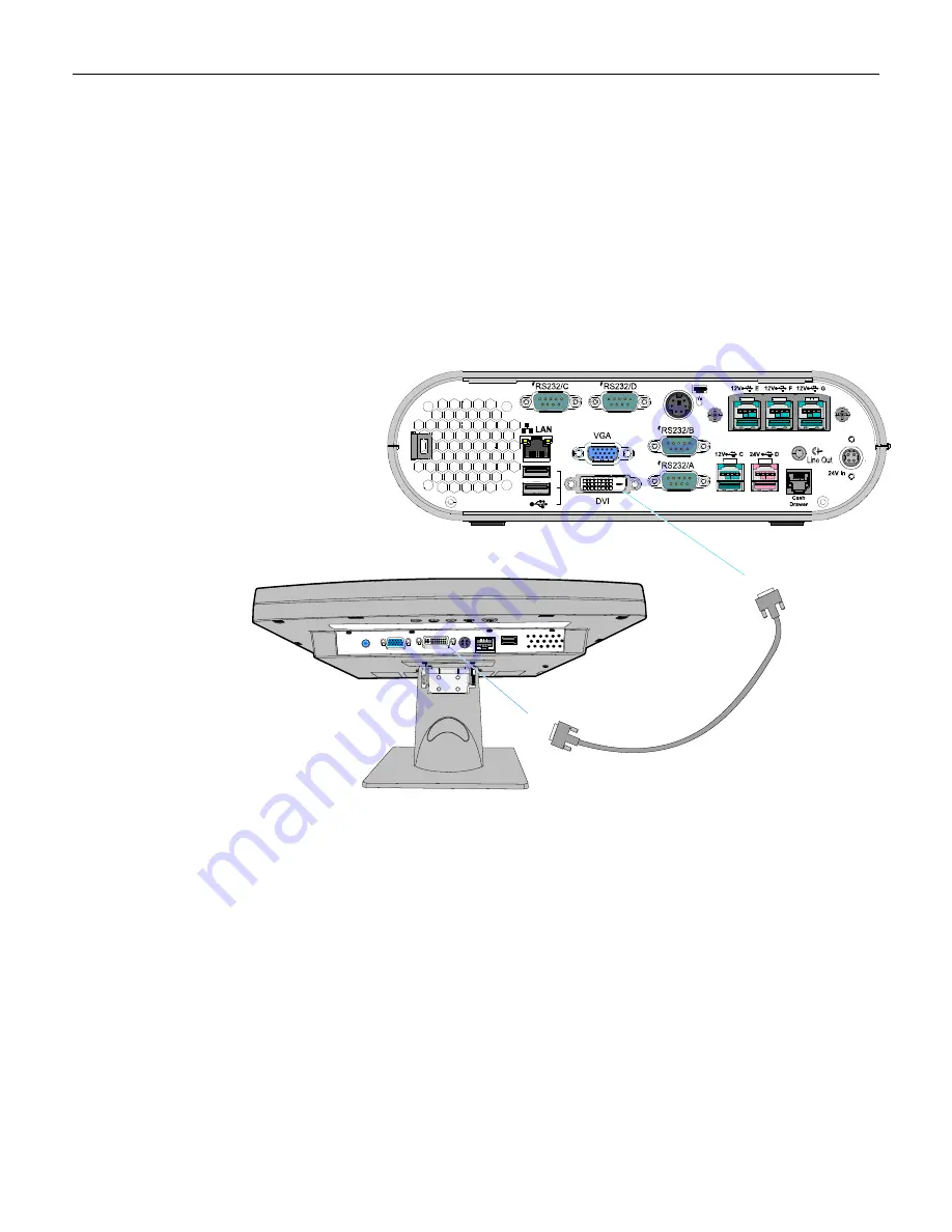
Installing a 5964 15-Inch LCD Touch Monitor 

There


are


two


cables


required


to


configure


a


5964


15

Inch


Touch


LCD.


DVI


or


VGA


cable


for


video


Power


Universal


Serial


Bus


(USB)


for


data


and


power


DVI Connections (Video) 

1.


Connect


the


DVI


Cable


to


the


DVI


connectors


on


both


the


5964


Touch


Monitor


and


the


RealPOS


40


terminal.


28670

A

B

DVI

DVI

497-0446721 - 1.0 m

(1432-C191-0010)

497-0446722 - 4.0 m

(1432-C191-0040)


Содержание RealPOS 40

Страница 1: ...NCR RealPOS 40 7600 Release 1 0 User Guide B005 0000 1974 Issue A ...

Страница 2: ...oducts as new technology components software and firmware become available NCR therefore reserves the right to change specifications without prior notice All features functions and operations described herein may not be marketed by NCR in all parts of the world In some instances photographs are of equipment prototypes Therefore before using this document consult with your NCR representative or NCR...

Страница 3: ...service technician Fuse Replacement Warning For continued protection against risk of fire replace only with the same type and ratings of fuse Attention Pour prévenir et vous protéger contre un risque de feu remplacer la fusible avec une autre fusible de même type seulement Lithium Battery Warning Warning Danger of explosion if battery is incorrectly replaced Replace only with the same or equivalen...

Страница 4: ... grounded in accordance with all local codes and ordinances Do not modify the plug provided if it will not fit the outlet have the proper outlet installed by a qualified electrician Improper connection of the equipment grounding conductor can result in a risk of electric shock The conductor with insulation having an outer surface that is green with or without yellow stripes is the equipment ground...

Страница 5: ...Label 1 11 Features 1 12 7600 Processor Board 1 12 Storage Media 1 12 Power Supply 1 12 Operating Systems 1 12 Power Management 1 13 G3 Mechanical Off 1 13 G2 S5 Soft Off 1 13 G1 Sleeping 1 13 G0 Working 1 13 ACPI Sleep States S0 S5 1 14 Enabling Wake on LAN 1 16 Windows 7 1 16 Windows XP 1 19 ACPI Processor C States 1 21 Operator Displays 1 22 NCR 5954 15 Inch DynaKey 1 22 5942 12 1 Inch Color LC...

Страница 6: ...dware Installation Installation Restrictions 2 1 Installing the Terminal 2 2 Installing the Keyboard and Mouse 2 3 Connecting AC Power 2 5 Installing the Transaction Printer 2 7 USB Installation 2 7 RS 232 Installation 2 8 Installing a 5942 15 Inch LCD Monitor 2 9 Installing a 5942 12 Inch Monitor 2 10 Installing a 5964 15 Inch LCD Touch Monitor 2 11 DVI Connections Video 2 11 VGA Connections Vide...

Страница 7: ... 3 2 Boot Menu 3 5 Security Menu 3 5 Chipset Menu 3 6 Chapter 4 Operating System Recovery Introduction 4 1 Prerequisites 4 1 OS Recovery Procedures for Windows XP 4 1 OS Recovery Procedures for Windows 7 Professional 4 3 Chapter 5 BIOS Updating Procedures Introduction 5 1 Prerequisites 5 1 Creating the Bootable Media 5 2 Creating a Bootable CD 5 2 Creating a Bootable USB Memory Drive 5 2 BIOS Upda...

Страница 8: ...7 Running the Scheduled Optimization Session 6 11 View Drive Information 6 13 SMART Attributes 6 16 Fast Diagnostic Scan 6 19 Error Messages 6 21 Full Diagnostic Scan 6 22 Error Messages 6 24 Frequently Asked Questions 6 25 Appendix A Powered Serial Port Settings Appendix B DOS Memory Settings Appendix C Disabling USB Ports for Security Purposes Revision Record Issue Date Remarks A Oct 2010 First ...

Страница 9: ...a small footprint that helps conserve valuable space at the Checkstand To complete your POS solution choose from NCR s extensive line of peripherals including printers displays keyboards and scanners The NCR RealPOS 40 enables you to protect your investment in legacy serial devices or choose from the growing list of USB peripherals The powered peripheral ports and 24V printer interface simplify ca...

Страница 10: ... 1 10 100 Ethernet 1 1 DVI D 1 1 VGA 1 1 Dual PS 2 1 1 Dual Cash Drawer 1 1 Optional Connectivity Extended I O card 3 12 volt USB 1 1 Storage Hard Disk Drive 2 5 SATA 3 0 Gbs 160GB N A Solid State Drive 2 5 SATA 3 0 Gbs N A 40GB CD ROM Drive External USB External USB PCI Expansion Slot N A N A Internal UPS N A N A External Power Supply 87 efficient MEPS Level V 1 1 Power Cords Order separately Ord...

Страница 11: ...ver ENERGY STAR compliant computers can save even more energy by using ENERGY STAR power management features which allow the computer to enter a very low power mode when not in use for a specified period of time The EPA estimates that these power management features when enabled on ENERGY STAR qualified computers could save you up to 115 kWh of electricity annually per unit This is equivalent to S...

Страница 12: ...System Tools section c Expand Mice and other pointing devices and then right mouse click on USB Touch Screen Controller d Select the Power Management tab The Allow this device to bring the computer out of standby option is active by default Un check the check box ...

Страница 13: ...device to bring the computer out of standby option as discussed in Step 1 above 4 If wake from standby via Touch is required the Touch Display must be powered from an independent source such as a power brick If the Touch Display is powered by power brick issues noted in 1 2 and 3 no longer apply More Information about Energy Star ENERGY STAR compliant systems combined with power management setting...

Страница 14: ...mallest form factor in its class and offers versatile configuration and mounting options Choose from NCR s extensive line of peripherals including printers displays keyboards and scanners The RealPOS 40 provides flexible connectivity options to power peripherals as well as dual display support for customer facing advertising and messaging The system can be configured modularly or stacked on an NCR...

Страница 15: ...Chapter 1 Product Overview 1 7 Stacked Configuration An optional stand is available to mount the terminal vertically Vertical Stand Configuration ...

Страница 16: ...ote The cell colors indicate the color of the LED at that particular time Current System Operation Suspect Component System State Power LED Disk Activity LED Corrective Action Normal Operation N A System ON ON OFF N A Normal Operation N A System ON with HDD activity ON Flashing HDD Access N A Normal Operation N A Unit in Suspend S3 Blinking 1 sec ON N A OFF AC Present N A OFF Not in Standby Extern...

Страница 17: ...mbient temperature 3 Check cooling components POST CPU CPU not operating ON ON 1 Check for correctly installed CPU 2 Replace Motherboard POST BIOS Chip BIOS Checksum failure ON Flashing 4 sec 1 Perform BIOS crisis recover 2 Replace BIOS chip 3 Replace Motherboard POST Memory Memory issue ON Flashing 1 sec 1 Check for properly installed memory 2 Replace memory 3 Replace Motherboard POST Motherboard...

Страница 18: ...3 Replace or re image HDD 4 Replace Motherboard LAN is Boot Device 1 Check for LAN link and activity LEDs on the Back Panel 2 Check LAN cable 3 Replace Motherboard Cabinet Security The 7600 has easy access to the internal components However the case can be secured to a fixed object desk pole etc by attaching a standard Kensington lock to the Security Hasp In addition a small padlock can be attache...

Страница 19: ... included if the terminal is ordered and shipped with a pre installed Microsoft Operating System There are two types of Microsoft COA stickers Depending on the Microsoft Operating System ordered the label is located on either the Bottom Cover for XP Professional and Windows 7 OR next to the Certification Label for XP Embedded WEPOS POSReady 2009 and POSReady 7 28563 Model Serial Number Label Certi...

Страница 20: ...ble One 12V USB Power port One 24V USB Power port Dual cash drawer support from one connector using Y cable Audio Line Out Three 12V USB Power ports on a USB Daughter Card Optional DC Power Jack for Power Brick Storage Media Primary 2 5 SATA Hard Drive Solid State Drive SATA interface Power Supply 150W Output power Switching Power Supply External 24V Adapter MEPS Level V mark efficiency 87 minimum...

Страница 21: ...es a large latency in order to return to the Working state The system s context will not be preserved by the hardware The system must be restarted to return to the Working state It is not safe to disassemble the machine in this state G1 Sleeping A computer state where the computer consumes a small amount of power user mode threads are not being executed and the system appears to be off from an end...

Страница 22: ...trol starts from the processor s reset vector after the wake event In NCR systems during S3 power is only provided to the on board USB ports Note When the terminal resumes from an S3 state all the USB devices re enumerate This causes speaker tones as if they were disconnected and then reconnected This does not present a problem and the USB devices will continue to operate correctly Requirements fo...

Страница 23: ...y data to HDD CPU halted OFF Note Some devices remain powered by standby voltage LAN USB to allow wake up Power Supply Status On On Powered Down Powered Down Powered Down Power Consumption 37 24 2 1 1 Wake Options Power Switch N A Y Y Y Y PS 2 Keyboard N A Y Y Y Y PS 2 Mouse N A Y N N N USB Keyboard N A Y Per O S N N USB Mouse N A Y Per O S N N LAN magic packet N A Y Y Y Y RTC Alarm N A Y Y Y Y Se...

Страница 24: ...st be enabled factory default The procedure for enabling the driver depends on which operating system you are using Windows 7 1 Select Start Computer System Properties Tab Device Manager 2 Select Network adapters and then 3 Right mouse click the Realtek PCIe FE Family Controller driver and then select Properties ...

Страница 25: ...Chapter 1 Product Overview 1 17 4 Under the Advanced tab both Wake on Magic Packet and Wake on Pattern Match be Enabled Select OK after making any changes should ...

Страница 26: ...1 18 Chapter 1 Product Overview 5 Under the Power Management tab all option boxes should be checked Select OK after making any changes ...

Страница 27: ...ct Overview 1 19 Windows XP 1 Select Start Control Panel Hardware Tab Device Manager button 2 Select Network adapters and then 3 Right mouse click the Realtek PCIe FE Family Controller driver and the select Properties ...

Страница 28: ...erview 4 Under the Advanced tab the Wake on Magic Packet should be Enabled Select OK after making any changes 5 Under the Power Management tab the option boxes as shown below should be checked Select OK after making any changes ...

Страница 29: ...a sleeping state the processor does not execute any instructions Each processor sleeping state has a latency associated with entering and exiting that corresponds to the power savings In general the longer the entry exit latency the greater the power savings when in the state To conserve power OSPM places the processor into one of its supported sleeping states when idle While in the C0 state ACPI ...

Страница 30: ...te USB DynaKey requires Windows XP XPe The combined display and keypad is designed to reduce operator training time simplify complex POS transactions and improve associate cashier productivity Combined with the appropriate applications software the DynaKey can virtually eliminate the need for an operator to memorize function key locations and sequence The USB DynaKey interfaces with the host termi...

Страница 31: ...e small footprint and ergonomic packaging of LCD technology versus traditional CRT s Depending on the customer s requirements this LCD display can be used either as an operator display or a customer information display CID The 5942 Display features a 12 1 Inch Active Matrix Color LCD with support for SVGA and XGA resolution 5942 15 Inch Color LCD ...

Страница 32: ...4 8xxx is a 15 inch XGA 1024x768 Liquid Crystal Display with either a resistive or capacitive Touch Screen for operator input Features 15 LCD XGA 1024x768 native resolution 350 nit typical brightness also supports VGA SVGA SXGA Dual Bulb adjustable brightness Capacitive or 5 wire resistive touch options USB interface Video VGA standard 15 pin female Integrated stereo speakers volume controlled via...

Страница 33: ...24 768 resolution Pixel Configuration RGB vertical stripe Supported Colors 16 2 Million 6 bits FRC Display text modes supported SVGA 800 600 pixel XGA 1024 768 pixel VGA 640 480 pixel SXGA 1280 x 1024 images to full screen size Moisture dust sealed display between touchscreen display OSD controls to allow display adjustments Auto selection DC voltage input to allow connection of 12V or 24v option ...

Страница 34: ...T LCD also supports VGA SVGA Resolutions 5 Wire Resistive Touch USB Interface Video VGA Standard 15 Pin Female Integrated Stereo Speakers Power Supplied via AC Line Input or 12 DC Power Brick VGA Touch Speaker and Power Cables Remote Table Top Mount Optional MSR Field Installable USB Interface VESA standard 75mm mounting pattern on the back of the enclosure Uses NCR s industry standard OPOS and Ja...

Страница 35: ...Chapter 1 Product Overview 1 27 NCR 5982 6 5 Inch LCD Display The 5982 LCD Display is a terminal powered color 6 5 Inch VGA LCD ...

Страница 36: ...alPOS 40 supports the following NCR 5932 Keyboards NCR 64 Key PS 2 POS Keyboard 5932 2xxx NCR USB Alphanumeric Big Ticket Keyboard 5932 5xxx NCR 5932 66xx 104 Key Programmable POS Keyboard Keyboard Power The RealPOS 80 supplies power to the PS 2 keyboard even when in the OFF state This is for configurations that require the terminal to turn on when a key is pressed Most NCR PS 2 keyboards have a P...

Страница 37: ...anner connector Please refer to the Wedge Software User s Guide BD20 1368 A for detailed information about interfacing and configuring these devices Keylock The Big Ticket and 64 key keyboards have a four position keylock switch The table following explains the keylock positions Abbreviation Position Description Ex Exception Used by the customer or service representative to perform low level progr...

Страница 38: ...wer on Red Wedge controller reporting an error condition Flashing red green Keypad of 64 key keyboard in PC Setup mode Off System off see Keyboard Power section Note For more information about the Wedge controller refer to Wedge Software User s Guide BST0 1368 B MSR Magnetic Stripe Reader The MSR is an optional feature that provides support for reading magnetically coded data cards The keyboards s...

Страница 39: ...ains the key matrix and other POS specific functions such as keylock speaker system status indicator and magnetic stripe reader MSR This 5932 keyboard also has a USB port to connect a Scanner or other USB device Features The NCR 5932 USB Keyboard supports the following features Integrated Touch Pad Keylock Speaker 3 Track Magnetic Stripe Reader MSR Keyboard Status LEDs USB cable Additional externa...

Страница 40: ...ultifunctional keyboard that is two keyboards built into one The keyboard consists of two major sections 32 key Point Of Sale Keyboard PC type Alphanumeric Keyboard 29168 Keylock Glide Pad MSR The keyboard includes the following features Keylock Tone Indicator Keyboard Status Indicator Magnetic Stripe Card Reader MSR Glide Pad ...

Страница 41: ...eyboard is a multifunctional keyboard that is two keyboards built into one The keyboard consists of two major sections 32 key Point Of Sale Keyboard PC type Alphanumeric Keyboard The keyboard includes the following features Keylock Tone Indicator Keyboard Status Indicator Magnetic Stripe Card Reader MSR Glide Pad ...

Страница 42: ...rve as a display for any industry standard PC It is a Vacuum Fluorescent Display VFD 5975 1000 2x20 VFD G11 5975 1001 2X20 VFD CG1 There are four post options available in 4 inch increments Features Display 2X20 Character Vacuum Fluorescent Display VFD 7X9 pixel characters Character height Minimum 9mm Maximum 11mm PCB Microcontroller EIA 232 Interface support USB 2 0 Interface support ...

Страница 43: ...or USB 2 0 I F support The components for both interfaces are populated on a single printed circuit board Both interfaces are active though only one interface can be physically connected at a time The display communicates via the interface connected to it Mounting Options Table Mount 4 in Post Table Mount 8 in Post Table Mount 12 in Post Table Mount 16 in Post Integrated Mount for NCR 7456 7457 74...

Страница 44: ...lti function printer It prints receipts validates and prints checks and prints on a variety of single or multiple part forms There is not journal as it is kept electronically by the host terminal The printer can connect through a USB port or a serial port It can receive power from a power supply or through a USB power cable ...

Страница 45: ...terface allows the 7168 to be connected to any host computer that uses RS 232C or USB communication interface The receipt station uses thermal printing technology Therefore there is no ribbon cassette to change and paper loading is extremely simple Printing on single or multiple part forms validating checks and printing checks is also easy in the accommodating slip station Another feature is the M...

Страница 46: ...SB port or a serial port It receives power from the 24V connector on the terminal or from an external power supply NCR 7198 Printer The NCR 7198 printer is a fast quiet relatively small and very reliable printer with front and back printing on the receipt paper capability The printer can connect through a USB port or a serial port It can receive power from a power supply or through a USB power cab...

Страница 47: ...the NCR Workstation and Peripheral AC Wiring Guide BST0 2115 53 Install the RealPOS 40 near an electrical outlet that is easily accessible Use the power cord as a power disconnect device Do not permit any object to rest on the power cord Do not locate the RealPOS 40 where the power cord can be walked on Use a grounding strap or touch a grounded metal object to discharge any static electricity from...

Страница 48: ...npack the terminal in the desired location 2 Connect the external cables to the connectors located on the rear of the unit There is also a USB connector on the Front Panel See the following sections for each component 28047 USB 12V E 12V F12V G 12V C 24V D B A 24V ...

Страница 49: ... supports USB and PS 2 type keyboards Only USB mice are supported See the following examples of supported configurations 28572 A B USB Keyboard and USB Mouse 28573a A B PS 2 Keyboard and USB Mouse Note PS 2 Extension Cables cannot be used with a PS 2 Keyboard that has a Glide Pad ...

Страница 50: ...2 4 Chapter 2 Hardware Installation 28575 A B USB Keyboard w Glide Pad ...

Страница 51: ...n The 7600 requires the NCR 24 V power supply that is shipped with the terminal Use of other power bricks may cause damage to the unit 1 Connect the Power Supply cable to the DC Power connector on the terminal 2 Connect the AC Power Cord to the Power Supply and to an AC outlet 28689 A B AC Power Cord Country Specific ...

Страница 52: ...ower Cable connector locks into position when connected to the terminal and cannot be removed by simply pulling on the cable You must grasp the connector and slide the outside housing out from the terminal to unlock it from the terminal connector 28690 Terminal Power Cable ...

Страница 53: ... a USB connector or an RS 232 connector USB Installation Connect the Powered USB Printer Interface Cable to the USB Connector and Power Connector on the printer and to the 24 V Powered USB Connector on the terminal 28576 A B Power USB 24V USB 497 0441177 1 m 1432 C088 0010 497 0473052 4 m 1432 C404 0040 ...

Страница 54: ...nector on the terminal Note The factory default setting for the RS 232 ports is powered See the Appendix Powered Serial Port Settings 2 Connect the Powered USB Printer Interface Cable to the Power Connector on the printer and to the 24V Powered USB Connector on the terminal 28577 A B Power RS 232 24V USB 497 0441156 1m 1432 C092 0010 497 0441157 4 m 1432 C092 0040 RS 232 ...

Страница 55: ...D Monitor receives video through the VGA interface Power is received from an AC power source 28598 A B VGA AC Power Cord Country Specific AC 1 Connect the Video Cable from the 5942 to the VGA connector on the RealPOS 40 terminal 2 Connect the AC Power Cable to the 5944 and to an AC power source ...

Страница 56: ... VGA interface Power is received from the terminal using a powered USB cable 28581 A B VGA VGA Power USB 497 0428512 4 m 1416 C851 0040 3 Connect the Video Cable to the VGA connectors on the 5942 monitor and RealPOS 40 terminal 4 Connect the Powered USB Cable to the 5942 and to the Powered 12V USB connector on the terminal ...

Страница 57: ...figure a 5964 15 Inch Touch LCD DVI or VGA cable for video Power Universal Serial Bus USB for data and power DVI Connections Video 1 Connect the DVI Cable to the DVI connectors on both the 5964 Touch Monitor and the RealPOS 40 terminal 28670 A B DVI DVI 497 0446721 1 0 m 1432 C191 0010 497 0446722 4 0 m 1432 C191 0040 ...

Страница 58: ...are Installation VGA Connections Video 1 Connect the VGA Cable to the VGA connectors on both the 5964 Touch Monitor and the RealPOS 40 terminal 28578 497 0435044 1m 1416 C972 0009 497 0435045 4m 1416 C972 0040 VGA VGA A B ...

Страница 59: ...d USB Cable Connections Data and Power 1 Connect the Powered USB Cable to the 5964 and to one of the 12V Powered USB connectors on the RealPOS 40 terminal 28672 A B USB Power 497 0445076 1 m 1432 C156 0010 497 0445077 4 m 1432 C156 0040 12V USB ...

Страница 60: ... Hardware Installation NCR 5954 USB DynaKey Cable Connections The DynaKey connects to the terminal via two cables Digital Video Interface DVI or VGA cable for video Powered Universal Serial Bus USB for data and power ...

Страница 61: ...ter 2 Hardware Installation 2 15 DVI Cable Connections Connect the cable to the DVI connectors on the DynaKey and terminal A B 28675 DVI DVI 497 0446721 1 0 m 1432 C191 0010 497 0446722 4 0 m 1432 C191 0040 ...

Страница 62: ... 16 Chapter 2 Hardware Installation VGA Cable Connections Connect the cable to the VGA connectors on the DynaKey and terminal A B 28676 497 0435044 1m 1416 C972 0009 497 0435045 4m 1416 C972 0040 VGA VGA ...

Страница 63: ...ion 2 17 Powered USB Cable Connections Connect the Powered USB Cable to the DynaKey and to one of the Powered USB connectors on the terminal A B 28677 USB Power 497 0445076 1 m 1432 C156 0010 497 0445077 4 m 1432 C156 0040 12V USB ...

Страница 64: ...2 18 Chapter 2 Hardware Installation Installing a 5982 6 5 Inch LCD 1 Remove the Base from the Display 2 screws 23162 Screws ...

Страница 65: ...er cables up through the bottom of the Base and connect them to the Display Note The power cable can be either an External Power Supply or a Powered USB cable 23435 Power VGA 3 Install the Base to the Display 2 screws 4 Route the cables out the rear of the Base ...

Страница 66: ...nstallation 5 Connect the Power Cable External Power Supply a Connect the AC Cord to the Power Supply 28673 A B VGA AC Cord b Connect the VGA cable to the VGA port on the host terminal c Connect the power cable to an AC source ...

Страница 67: ...Chapter 2 Hardware Installation 2 21 Terminal Powered 7446 30303131 a Connect the Power Cable to the Powered 12V USB port on the host terminal 12V USB 28674 A B VGA ...

Страница 68: ... display mode can be a clone same video data displayed on both displays or an extended desktop the desktop spans across both displays The dual mode is configured using the Intel Graphics Media Accelerator control panel 1 Power down the system 2 Connect the secondary display Note Both displays must be connected to the 7600 before powering up the system 3 Apply power to the system 4 Right click the ...

Страница 69: ... Mode drop down menu select Intel R Dual Display Clone 2 Select the Primary Device Monitor or Digital Display 3 Select the Secondary Device Digital Display or Monitor 4 Select Apply 5 Select OK within 15 seconds to accept the new settings 6 Select OK to close the Control Panel ...

Страница 70: ...ay This display has the Start button and Taskbar 3 Select Secondary Device Digital Display or Monitor This display is the desktop extension You can re position the displays as desired by dragging the 1 or 2 icons in the Position box 4 Select Apply 5 Select OK within 15 seconds to accept the new settings 6 Select OK to close the Control Panel ...

Страница 71: ... Panel with specific keystrokes on the keyboard These hotkeys are listed in the Intel Control Panel under the Hot Keys tab The most useful Hot Keys are CTRL ALT F1 Monitor in single display mode CTRL ALT F4 Digital Display in single display mode Note The Hot Keys can be used to recover from a blank display in Windows This is true only if Windows Desktop loads completely meaning if Windows is waiti...

Страница 72: ...e Cash Drawer can connect to the Cash Drawer connector or to the transaction printer Note The 7600 is not designed for integration with any current NCR cash drawer The 7600 supports the following Cash Drawers 2185 Flip Top Drawer 2186 Compact Cash Drawer 2189 Full size Cash Drawer The Cash Drawer can be connected to the Back Panel on the 7600 or to the Cash Drawer Connector on the transacation pri...

Страница 73: ...Chapter 2 Hardware Installation 2 27 Installing Two Cash Drawers The 7600 supports a 2 drawer configuration with a Y cable 1416 C372 0006 28583 A B ...

Страница 74: ...1 Slide the Cover Latch located on the bottom of the unit forward to unlock the Top Cover Note First remove the Security Lock on the rear if present 28591 Cover Latch 2 Pivot the Top Cover open and gently rest it on the table surface Caution When opening the cover do not allow it to drop onto the table surface The mechanical shock can damage the HDD 28592 ...

Страница 75: ... bracket from the Top Cover and slide the HDD Bracket as shown until you see Unlocked displayed in the opening in the HDD Bracket 28593 HDD HDD Bracket 4 Remove the HDD from the Top Cover Bracket and disconnect the cables 28596 HDD Data Power Connector 5 Install the new HDD using the reverse procedure ...

Страница 76: ...2 30 Chapter 2 Hardware Installation ...

Страница 77: ...move the cursor to the Exit Menu select either Save Changes Exit or Save Changes and press Enter Restoring Factory Settings To reset all values to their default settings for the current screen press F9 and then Enter when the confirmation message is displayed The terminal automatically loads the BIOS default values To reset all BIOS settings to their default settings go to the Exit menu press F9 s...

Страница 78: ...nabled Intel R SpeedStep tm tech Enabled Intel R C STATE tech Enabled Enhanced C States Enabled IDE Configuration ATA IDE Configuration Enhanced Configure SATA 1 as AHCI SATA 0 Hard Disk Type Auto LBA Large Mode Auto Block Multi Sector Transfer Auto PIO Mode Auto DMA Mode Auto S M A R T Auto 32Bit Data Transfer Enabled SATA 1 Not Detected Type Auto LBA Large Mode Auto Block Multi Sector Transfer A...

Страница 79: ...e Health Monitoring Typical Acceptable Range CPU Temperature 51 C 125 F less than 65 C GMCH Temperature 50 C 122 F less than 65 C VRM Temperature 49 C 120 F less than 60 C Fan1 Speed N A no fan Fan1 Speed N A CPU Vcore 1 184 V 1 00 1 30 CPU VIT 1 056 V 0 90 1 20 3 30V 3 312 V 3 05 3 55 5 00V 4 972 V 4 60 5 40 12 0V 11 904 V 11 20 12 80 5Vsb 4 945 V 4 60 5 40 ACPI APM Configuration ACPI Aware O S Y...

Страница 80: ...ls LAN Wake Up From S5 Enabled Resume On Ring Disabled Resume On RTC Alarm Disabled USB Configuration Legacy USB Support Enabled Port 64 60 Emulation Disabled USB 2 0 Controller Mode HiSpeed BIOSEHCI Hand Off Enabled Legacy USB1 1 HC Support Enabled ...

Страница 81: ...Boot Order Defaults LAN First Boot Device Priority 1st Boot Device Network Realtek PX 2nd Boot Device SATA S0 TOSHIBA MK 3rd Boot Device USB name of device Hard Disk Drives 1st Drive SATA S0 TOSHIBA MK CD DVD Drive 1st Drive USB name of device Security Menu Supervisor Password Not Installed User Password Not Installed Change Supervisor Password Enter Change User Password Enter Boot Sector Virus Pr...

Страница 82: ... Function Configuration Boots Graphic adapter Priority PEG PCI DUMT Mode Select DUMT Mode DUMT FIXED Memory 128MB PAVP Mode Disabled Boot Display Device Auto Detect South Bridge Configuration USB 2 0 Controller Enabled Audio Controller Enabled LAN Controller Enabled SLP_S4 Min Assertion Width 1 to 2 seconds ...

Страница 83: ...D DVD drive 2 Connect a keyboard to the terminal 3 Apply power to the terminal 4 Press F8 during boot when you see the NCR logo to enter the Boot Select menu 5 Select USB name of device 6 You should see a message during boot indicating that the device has been recognized 7 At the menu enter 1 to select the image restore function and press Enter NCR Partition Image Application Select an option 1 Pr...

Страница 84: ...t after operation complete yes 6 Resize last data partition if possible no 7 Resize last data partition to Full Disk A Accept these arguments V View OS Documentation Q Quit and reboot 10 At the following prompt replace the CD with the next CD Press Enter to continue Automatic mount Please press ok to mount dev cdrom on mnt cdrom Ok 11 Repeat the previous step for each CD as required 12 Remove the ...

Страница 85: ...he 7600 1 Insert the NCR WIM Image Deployment Capture DVD D370 0893 0100 into the DVD drive 2 Connect a keyboard to the terminal 3 Apply power to the terminal 4 Press F8 during boot when you see the NCR logo to enter the Boot Select menu 5 Select USB name of device 6 You should see a message during boot indicating that the device has been recognized 7 At the options menu select Deploy NCR Official...

Страница 86: ... should be deployed Select the drop down box and then the location for the image Also select either the radio button to Reboot the terminal after the image has been installed or you can select Pause to view the statistics at the end of the image load When you have made your choices select Accept ...

Страница 87: ...Chapter 4 Operating System Recovery 4 5 9 The WIM application then deploys the NCR Official image on to the terminal The following displays while the terminal is loading ...

Страница 88: ...he message ʺPress OK to Rebootʺ Select OK 11 Remove the DVD before the system reboots 12 Complete the Windows 7 setup enter the time zone computer name accept the license etc Uncheck all the Security Warning message boxes about Always ask before opening this file as they appear and click Run for each of them ...

Страница 89: ...dure Prerequisites The following are required to perform a BIOS update Bootable USB CD ROM Drive Keyboard BIOS Software Download from the NCR website http www ncr com a At this site select the Support tab b Select Drivers and Patches Retail Support Files NCR RealPOS and SelfServ Terminal and Operating Systems NCR RealPOS 40 7600 BIOS c Select the desired BIOS File ISO Image Used with CD ROM boot d...

Страница 90: ...aded files 3 Copy the files to the root directory of the USB Memory Drive 4 Open a DOS command window 5 Change directory to the USB Memory Drive 6 Execute the following command Syslinux fma USB drive letter Example Syslinux sfma f This command erases any bootable methods that may be present on the USB drive and replaces it with the BIOS update process If the resulting USB memory drive is not boota...

Страница 91: ...Class Model Serial information This happens if the program detects invalid DMI information in the current BIOS or if you are replacing the processor board which has no Class Model Serial information in the BIOS Important DMI information is mandatory Interactive Method This method permits you to input replace the Class Model Serial information that is stored in the BIOS Note DMI information that is...

Страница 92: ...I only Serial Model Class update ONLY no BIOS or SPI Update This option lets you enter the DMI information only The SPI and BIOS are not updated 1 Highlight Option 2 and press ENTER 2 At the prompt press ENTER to enter the Class Model Serial Number information DMI Follow the onscreen format instructions Example 7610 1000 8801 ENTER 54 19378230 ENTER 3 Press 1 to confirm the data and to continue 4 ...

Страница 93: ...7610 1000 8801 ENTER 54 19378230 ENTER 3 Press 1 to confirm the data and to continue 4 The Flash Program updates the BIOS and automatically reboots the terminal Option 4 Update BIOS Default Serial Model Class information This option is for Service Personnel only It updates the BIOS but leaves the Class Model Serial fields empty erased The DMI information is then entered when the board is installed...

Страница 94: ...5 6 Chapter 5 BIOS Updating Procedures ...

Страница 95: ...drives SSDs because they offer higher levels of performance when they hold less data To remove this unwanted constraint Intel provides the Intel SSD Optimizer for its 34nm series of X25 M and X18 M solid state drives This feature gives the ability to retain out of box performance levels over the life of the drive Unlike traditional hard disk drives it is advantageous to tell an SSD when you delete...

Страница 96: ...he Intel SSD Toolbox download The Intel SSD Toolbox has the following installation requirements Microsoft Windows operating system Windows XP Windows Vista or Windows 7 32 64 bit NET Framework 2 0 Note If your system does not have NET installed the tool will direct you to the appropriate place to obtain it At least 10 megabytes MB of available space on the SSD To determine whether the SSD has enou...

Страница 97: ...fication when the tool cannot determine whether the drive has RAID or encryption The Intel SSD Optimizer will work on encrypted drives however there is no guaranteed way to determine in each case whether the drive has RAID or is encrypted so the tool will prompt the user to confirm Dynamic Disks The Intel SSD Toolbox will not work with any form of Dynamic Disks and displays the configuration as No...

Страница 98: ... Name EnableAutoLayout Type REG_DWORD Value 0 Windows Vista 7 To turn off the Disk Defragmenter program on computers with Microsoft Windows Vista or Windows 7 operating systems use the following instructions a From Start navigate to the Control Panel folder b Click System and Security and then Administrative Tools c Double click on Services then scroll down to Disk Defragmenter d Set Startup Type ...

Страница 99: ...are License Agreement click I Agree Then click Next e Either accept the default location or click Browse to identify where you want to store the installation folder Then click Next f Click Next to confirm the installation of the Intel SSD Toolbox g Click Close to exit the installation wizard Once the installation finishes the Intel SSD Toolbox will be installed at the following default location Pr...

Страница 100: ... the ATA and SATA capabilities for the drive Check SMART Attributes Lists the SMART features and their respective thresholds and if necessary indicates any action to take Run Fast Diagnostic Scan Analyzes the first 1 5 GB of the SSD to determine whether there are any READ or WRITE errors Run Full Diagnostic Scan Analyzes the complete SSD to determine whether there are any READ or WRITE errors or a...

Страница 101: ...anagement Tools The following screen is displayed Screen Button Definitions Schedule Defines when how often you want to automatically run the Intel SSD Optimizer on the selected SSD Back Returns to the main screen of the Intel SSD Toolbox program Stop Halts the running of the Intel SSD Optimizer on a selected SSD Run Launches the Intel SSD Optimizer on a selected SSD 2 Click Schedule to define a s...

Страница 102: ...you select the screen will change to request additional scheduling information Time Selects the time to run the tool Day Selects the day to run the tool Apply to Identifies whether the tool should be run only on a selected drive or on all SSDs in the system Currently Scheduled Sessions Lists any scheduled launches 4 After you have entered the appropriate schedule information click Add ...

Страница 103: ...ter 6 Solid State Drive Optimization 6 9 5 Click Schedule in the Information screen to add the newly defined session 6 The tool will then display the new schedule in the Currently Scheduled Sessions section ...

Страница 104: ...sessions are scheduled to run when the system is on The tool does not wake up or turn on the system to run an Intel SSD Optimizer session Avoid running the Intel SSD Optimizer when a backup is in session If your system uses Microsoft Windows 7 and the standard Microsoft AHCI driver the default setup for normal configurations without RAID the Intel SSD Optimizer will work however you do not need to...

Страница 105: ...tion 6 11 Running the Scheduled Optimization Session When the scheduled session starts a progress bar appears in the task tray notifying the user that the Intel SSD Optimizer is running Upon completion the status of the operation is shown ...

Страница 106: ...6 12 Chapter 6 Solid State Drive Optimization Manually Running an Optimization Session 1 From the Main Screen click on Intel SSD Management Tools The following screen is displayed 2 Click Run ...

Страница 107: ...id State Drive Optimization 6 13 View Drive Information Use this option to view the standard Identify Device information for the SSD 1 From the Main Screen click on View Information The following screen is displayed ...

Страница 108: ...6 14 Chapter 6 Solid State Drive Optimization 2 Scroll down the list to find the SSD information such as Serial Number Firmware Version and Model Number ...

Страница 109: ...tion and the SMART data to a cvs file Browse to the desired location and click Save to write the drive information Back Click Back to return to the Intel SSD Toolbox main screen Refresh Use this function to reissue the ATA IDENTIFY DEVICE command and redisplay the information for the selected drive ...

Страница 110: ...Main Screen click on Check SMART Attributes The following screen is displayed Spin Up Time The average time it takes the spindle to spin up Since a SSD has no moveable parts this attribute reports a fixed raw value of zero 0 and a fixed normalized value of 100 Use the Raw value for this attribute Start Stop Count This type of event is not an issue for SSDs However hard disk drives can experience o...

Страница 111: ...tribute C0 Unsafe Shutdown Count This attribute reports the cumulative number of unsafe unclean shutdown events over the life of the device An unsafe shutdown occurs whenever the device is powered off without STANDBY IMMEDIATE being the last command Use the Raw value for this attribute E1 Host Writes This attribute reports the total number of sectors written by the host system The raw value is inc...

Страница 112: ... only available for 34nm drives and counts the number of times errors are encountered during logical block addressing LBA tag checks on the data path within the drive Use the Normalized value for this attribute Export Use this function to write the drive information and the SMART data to a cvs file Browse to the desired location and click Save to write the drive information Back Click Back to retu...

Страница 113: ...s approximately three to five minutes to run 1 From the Main Screen click on Run Fast Diagnostic Scan The following screen is displayed 2 Click Start to launch the Fast Diagnostic Scan Diagnostic Lists the name of the available scans Status Reports the progress of the scan Initially blank the field is populated while running the scan Recommended Action Identifies whether the system can use the dri...

Страница 114: ...6 20 Chapter 6 Solid State Drive Optimization The results of the scan are indicated on the next screen A successful scan is listed in the Recommended Action column if it is successful ...

Страница 115: ...rmation under the Recommended Action heading Inadequate Amount of Free Space The scanned drive needs more free space before attempting to run the Fast Diagnostic Scan again No Partition The scanned drive does not contain a partition For the Fast Diagnostic Scan to function properly the scan requires a partitioned area to create and validate the one gigabyte 1 GB of random data ...

Страница 116: ...can take an hour or more to run depending on the amount of free space on the drive 1 From the Main Screen click on Run Full Diagnostic Scan The following screen is displayed 2 Click Start to launch the Full Diagnostic Scan Diagnostic Lists the name of the available scans Status Reports the progress of the scan Initially blank the field is populated while running the scan Recommended Action Identif...

Страница 117: ...Chapter 6 Solid State Drive Optimization 6 23 The results of the scan are indicated on the next screen A successful scan is listed in the Recommended Action column if it is successful ...

Страница 118: ...rmation under the Recommended Action heading Inadequate Amount of Free Space The scanned drive needs more free space before attempting to run the Full Diagnostic Scan again No Partition The scanned drive does not contain a partition For the Full Diagnostic Scan to function properly the scan requires a partitioned area to create and validate the one gigabyte 1 GB of random data ...

Страница 119: ... RAID array Clicking accept will optimize the drive successfully On Microsoft Windows XP it works with no additional user input required Can I use the Intel SSD Optimizer if I have multiple Intel SSDs configured as part of a RAID set Current implementation of the Intel SSD Toolbox does not support SSDs configured as part of an OS RAID set Intel is looking at including support in future versions of...

Страница 120: ...es optimal performance levels over the life of the drive If I never delete files from my system will I see a benefit from the Intel SSD Optimizer While there should still be some benefit related to OS level cleanup of temp files temp directories and installers the Intel SSD Optimizer will result in higher levels of performance if unwanted files are deleted In order to see the most benefit it is re...

Страница 121: ... on the 7600 can be configured as powered or not The default setting for all the ports is 12 V powered To change the settings open the Top cover and change the jumpers on the Motherboard using the illustrations below 28688 12V E 12V F 12V G 12V C 24V D B A 24V ...

Страница 122: ...1 2 Appendix A Powered Serial Port Settings 28687a Default setting Ring Indicator 12 V 5 V COMD COMC COMA COMB ...

Страница 123: ...ver should be loaded in the CONFIG SYS file with the following DEVICE DOS EMM386 EXE NOEMS i B000 B7FF i D000 DFFF Other memory range Considerations B800 to BFFF Standard color graphics data area off limits C000 to CEFF VGA BIOS area off limits CF00 to CFFF PXE UNDI 4K E000 to FFFF PC BIOS area off limits ...

Страница 124: ......

Страница 125: ...ystem changes 1 Select Control Panel System Device Manager 2 Scroll down to and expand Universal Serial Bus Controllers 3 There are four Intel Host Controllers Universal Host Controller 27C8 Controls USB Ports A and B Universal Host Controller 27C9 Controls USB Ports C and D Universal Host Controller 27CA Controls USB Ports E and F Universal Host Controller 27CB Controls USB Ports G and H includes...

Отзывы: