background image


NCR Orderman Columbus800                             User Guide V01.00 

  Dimensions 

Orderman GmbH (Part of NCR Corporation) 

51                               


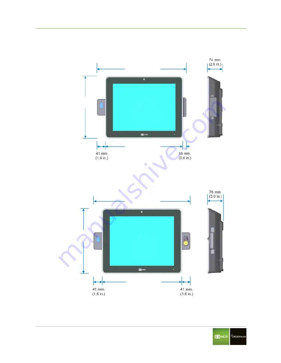
Terminal with MSR and Sidecar 

Fig. 49: Dimensions with MST and Sidecar  


Terminal with 2in1 Waiterlock and Sidecar 

Fig. 50: Dimensions with 2in1 Waiterlock and Sidecar  


12“ 377 mm (14.9 in.) 
15“ 437 mm (17.2 in.) 

12“ 321 mm (12.6 in.) 
15“ 378 mm (14.9 in.) 

12“ 269 mm (10.6 in.) 
15“ 304 mm (12 in.) 

12“ 269 mm (10.6 in.) 
15“ 304 mm (12 in.) 

12“ 321 mm (12.6 in.) 
15“ 378 mm (14.9 in.) 

12“ 403 mm (15.9 in.) 
15“ 460mm (18.1 in.) 

Содержание Columbus 800

Страница 1: ...NCR 2015 All rights reserved User Guide NCR Columbus800 Version 01 00...

Страница 2: ...Orderman accepts no responsibility for any damage or losses that arise from the use of this manual Orderman accepts no responsibility for any losses or claims by third parties that arise through the u...

Страница 3: ...____18 3 2 Power LED ______________________________________________________________________18 3 3 Label Locations __________________________________________________________________19 4 Hardware Instal...

Страница 4: ...__________________________________________________________48 10 Dimensions 50 10 1 Mounting Height__________________________________________________________________55 10 2 Power Supply Dimensions ____...

Страница 5: ...del number P1535 Version this manual applies to both versions 1 1 Warranty All warranty claims must be addressed to your local Orderman contractual partners 1 2 Serial Number and Labeling The labeling...

Страница 6: ...r serious damage to property can occur Warnings are highlighted by horizontal lines above and below the text Danger Danger means that serious personal injury can occur In particularly serious cases th...

Страница 7: ...ructions Il y a danger d explosion s il y a remplacement incorrect de la batterie Remplacer uniquement avec une batterie du m me type ou d un type recommand par le constructeur Mettre au r but les bat...

Страница 8: ...ave the proper outlet installed bya qualified electrician Improper connection of the equipment grounding conductor can result in a risk of electric shock The conductor with insulation having an outer...

Страница 9: ...800 is a Point of Sale POS teriminal designed for the restaurant and foodservice environment The terminal utilizes a next generation Intel Celeron Processor N3160 Quad core 2 24 GHz The highly efficie...

Страница 10: ...s to ease use and decrease training time for retail employees or to directly engage the consumer Software adjustable Brightness and Contrast Control for Main Display Better display characteristics for...

Страница 11: ...sure that is built to withstand tough in store conditions with continuous operation The fanless configuration increases reliability by preventing forced air through the unit thereby reducing contamina...

Страница 12: ...us800 User Guide V01 00 NCR Orderman Columbus800 Orderman GmbH Part of NCR Corporation 12 2 3 Mounting Configurations Fig 3 Columbus800 Mounting Configurations P Series Stand Wall Mount with Extension...

Страница 13: ...2 4 Customer Display Options Fig 4 Columbus800 Display Options Integrated 2x20 Customer Display 2x20 Customer Display on P Series Stand XD10 Customer Display on P Series Stand 2x20 Customer Display 2...

Страница 14: ...f NCR Corporation 14 2 5 Right Side Features Port A Fig 5 Columbus800 Port A Features 2 6 Left Sidecar Features Port B Fig 6 Columbus800 Port B Features SPI 3 Track Encrypted MSR 2in1 Waiter Lock Biom...

Страница 15: ...Strength Blend Environmentally Sealed Camera High Speed USB 2 0 1920 x 1080 FHD 2 0M optional Mini PC Wireless Dual Stream Dual Band 802 11 a g n 2x2 and 2 4 5 GHz optional Serial Port 3 RJ12 12V 2 R...

Страница 16: ...idecar with P Series Stand 12 L x 15 W x 15 5 H 30 4 cm L x 38 1 cm W x 38 4 cm H without P Series Stand 12 L x 15 W x 2 9 H 30 4 cm L x 38 1 cm W x 7 4 cm H 12 inch Display no MSR or Sidecar with P S...

Страница 17: ...7 Features Specifications Storage Temperature 0 C 45 C 32 F 113 F Note Must be in original packaging material in a humidity and temperature controlled environment Humidity 5 to 85 non condensing Envir...

Страница 18: ...d the Cable Cover Fig 7 Columbus800 Power Switch 3 2 Power LED Fig 8 Columbus800 Power LED The Front Panel Power LED has multiple functions as defined below Color Description Black System OFF or NO Po...

Страница 19: ...rman Columbus800 User Guide V01 00 Operator Controls Orderman GmbH Part of NCR Corporation 19 3 3 Label Locations Fig 9 Columbus800 Labels Serial Number Label Model Number Label Certification Label CO...

Страница 20: ...ccidental disconnects and tampering The strap is opened peripheral connections are made the strap is closed and then cables are then routed thorough the slot in the base Footprint An area of no less t...

Страница 21: ...ader head Biometric Cleaning Periodically the biometric reader may need to be cleaned depending on usage For this optical reader it is recommended to apply the sticky side of a piece of adhesive cello...

Страница 22: ...light If possible avoid reflective glaring caused by electric light sources Position the terminal for ideal viewing angles Fig 10 Ergonomics 4 3 Installing the Terminal The terminal can be mounted us...

Страница 23: ...er supply that is shipped with the terminal Use of other power supply may cause damage to the unit Do not connect or disconnect the 19V or 24V Power Cable from the terminal with the AC Power Cord stil...

Страница 24: ...bH Part of NCR Corporation 24 4 Loosen the Thumbscrew that secures the Base Cover Fig 13 Loose Thumbscrew 5 Slide the Base Cover toward the front slightly to disengage it from the Base Fig 14 Slide Ba...

Страница 25: ...rdware Installation Orderman GmbH Part of NCR Corporation 25 Fig 15 Route Power Cord 7 Attach the Power Cord to the Power Brick Fig 16 Attach Power Cord 8 Install the Power Brick in the Base Fig 17 Po...

Страница 26: ...the CableLock Cover Thumbscrew Fig 18 Open CableLock TM 10 Secure the excess power cables with a cable tie and route the cables behind the CableLock Cover Fig 19 Route Cables 11 Close the CableLock Co...

Страница 27: ...tion 27 4 5 Connecting the Peripheral Cables 1 Loosen the screw on the Terminal Cable Cover To open press on the indentations in the Cable Cover to unlatch the cover and then pivot the cover open Fig...

Страница 28: ...ing Cables are routed out the opening in the Cable Cover and down through the P Series Stand 1 Pivot the display toward the back Fig 22 Pivot display 2 Remove the Upper Stand Cover by pivoting it away...

Страница 29: ...Corporation 29 3 Open the CableLock Cover Thumbscrew Fig 24 Open CableLock TM 4 Route the cables down through the opening in the base of the stand Fig 25 Route Cables 5 Close the CableLock Cover and...

Страница 30: ...rdware Installation Orderman GmbH Part of NCR Corporation 30 4 7 Installing a Cash Drawer The Cash Drawer can be connected to the Cash Drawer connector or to the transaction printer Fig 26 Cash Drawer...

Страница 31: ...rminal to unlock it and then pull it out of the terminal connector 4 9 Connecting to a Network Most business configurations requires you to connect your Columbus800 system to a network Connecting to a...

Страница 32: ...ng on your installed operating system and your selected settings your system will vary in the amount of time it takes to boot up 4 11 Using External Connectors In order to use the Columbus800 system t...

Страница 33: ...the device from NCR POS terminal serial RJ12 connector order the following items below These kits are applicable to pin pads and scanners RJ12 to DB9M Adapter Kits 1639 K159 DB9M to RJ12 Adaptor CN100...

Страница 34: ...GND RX 4 3 TX TX 3 2 RX GND 2 5 GND RTS 1 8 CTS 1 6 RJ12 DB9 5 1 6 9 4 11 2 RJ45 Serial Port The port has a shunt to select between 12V 5V or normal RI functionality The default will be 12V Maximum po...

Страница 35: ...5 connector order the following items below RJ15 Adapter Kits 1639 K332 RJ45 to DB25 Adapter Cable 1 85m 1639 K333 RJ45 to DB9 Adapter Cable 1 85m RJ45 RS232 DB25 Printer Cable Signal Pin RJ45 Pin DB2...

Страница 36: ...SB port is capable of supplying 5V at 900mA max Pin Diagram Pin Signal Name 1 VBUS 2 D 3 D 4 GND 5 StdA_SSRX 6 StdA_SSRX 7 GND_DRAIN 8 StdA_SSTX 9 StdA_SSTX Shell Shield 4 11 4 Cash Drawer Kick Out CD...

Страница 37: ...ignment of the different Options The following options will use virtual comports for access except the integrated Customer Display that uses a physical comport see table below Comport assignments 2in1...

Страница 38: ...System Setup This varies from OS to OS but the following is typical 2 The initial setup procedures are performed Starting Windows Preparing the computer for first time Checking video performance 3 At...

Страница 39: ...vents are necessary for cooling Fig 30 Airflow Warning Do not place the terminal in an enclosed area where sufficient ventilation is not available Leave at least 100 mm 4 inches of clearance from air...

Страница 40: ...90 Watts or 150 Watts and provides power to the terminal and its powered peripherals Power Supply Range Input Current Max 90 Watts LOW 115 1 5 A HIGH 230 0 8 A 150 Watts LOW 115 2 2 A HIGH 230 1 2 A W...

Страница 41: ...unt Expansion 8 1 Installation Procedure 1 Secure the VESA Mount with UP arrow pointing up to the vertical surface using lag screws 4 Make sure you install the screws into the studs or that you use ha...

Страница 42: ...ews 2 Pivot the bottom end of the module up and then remove the extensions on the top end from the slots in the rear cabinet Fig 33 Remove Expansion Module 3 Install the Wall Mount Bracket with the th...

Страница 43: ...the brackets with the thumbscrew Fig 35 Hang on VESA Mount 8 2 Power Supply Bracket Fig 36 Power Supply Bracket 1 Attach the Power Supply Bracket beside the VESA Mount a Loosen the screws 2 of the VES...

Страница 44: ...de V01 00 Installing Wall Mount with Expansion Orderman GmbH Part of NCR Corporation 44 Fig 37 Attach Power Supply Bracket 2 Insert the power supply into the bracket AC Connector on top Fig 38 Insert...

Страница 45: ...Mount with Expansion Orderman GmbH Part of NCR Corporation 45 3 Replace the front cover of the bracket Fig 39 Replace Front Cover 4 Secure the bracket with the thumbscrew and the AC Power Cord with a...

Страница 46: ...sion 9 1 Installation Procedure 1 Secure the VESA Mount with UP arrow pointing up to the vertical surface using lag screws 4 Make sure you install the screws into the studs or that you use hardware of...

Страница 47: ...ith thumbscrew facing up onto the back of the terminal with the supplied screws 8 Fig 42 Install Spacer 3 Hang the terminal on the VESA Mount Insert the mushroom studs on the Wall Mount into the elong...

Страница 48: ...e VESA Mount Loosen the screws 2 of the VESA Mount Hook the Power Supply Bracket over the screws Retighten the screws Note To install the Power Supply Bracket independently from the VESA Mount refer t...

Страница 49: ...Mount with no Expansion Orderman GmbH Part of NCR Corporation 49 3 Replace the front cover of the bracket Fig 46 Replace Front Cover 4 Secure the bracket with the thumbscrew and the AC Power Cord with...

Страница 50: ...ig 47 Dimensions with MSR no Sidecar Terminal with 2in1 Waiterlock and No Sidecar Fig 48 Dimensions with 2in1 Waiterlock no Sidecar 12 337 mm 13 2 in 15 396 mm 15 6 in 12 321 mm 12 6 in 15 378 mm 14 9...

Страница 51: ...mensions with MST and Sidecar Terminal with 2in1 Waiterlock and Sidecar Fig 50 Dimensions with 2in1 Waiterlock and Sidecar 12 377 mm 14 9 in 15 437 mm 17 2 in 12 321 mm 12 6 in 15 378 mm 14 9 in 12 26...

Страница 52: ...Part of NCR Corporation 52 Terminal on the P Series Stand Fig 51 Dimensions on P Series Stand LCD Customer Display on the P Series Stand Fig 52 Dimensions with LCD Customer Display on P Series Stand 1...

Страница 53: ...sions Orderman GmbH Part of NCR Corporation 53 XD10 LCD Customer Display on the P Series Stand Fig 53 Dimensions with XD10 Display on P Series Stand LCD Customer Display on the Extension Arm Fig 54 Di...

Страница 54: ...800 User Guide V01 00 Dimensions Orderman GmbH Part of NCR Corporation 54 XD10 LCD Customer Display on the Extension Arm Fig 55 Dimensions XD10 Display with Extension Arm Wall Mount Dimensions Fig 56...

Страница 55: ...should be appropriate for the majority of users Based on the recommendation of the ADA America Disability Association It is recommended that the system is approximately 1220 mm 48 in from the floor to...

Страница 56: ...NCR Orderman Columbus800 User Guide V01 00 Dimensions Orderman GmbH Part of NCR Corporation 56 10 3 Power Supply Bracket Fig 59 Dimensions Power Supply Bracket Screws...

Страница 57: ...sk Checkdisk will check the consistency of the SSD and also the Windows filesystem It can happen that Windows itself will create a failure in the Windows filesystem and that Windows will not start Che...

Страница 58: ...destination Network Local Drive or USB Note Windows 7 image requires a minimum of 4 GB space available on the network Local Drive or USB drive POSReady requires a minimum of 2 GB Please make sure enou...

Страница 59: ...kup strategy should be 1 Original factory image this is the backup of the original preinstalled Windows7 POS image 2 Site image after the dealer has installed and setup the whole machine for a site it...

Страница 60: ...the original factory image which was preinstalled by Orderman 2 Site image this will load the site image The box is grey because no site image is stored on this storage media 3 User image this will l...

Страница 61: ...arious posibilities to protect the POS Application e g Dongle Serial Number via DatabaseThe Orderman Recovery Tool doesn t have an influence how the POS Application is protected Note If you set the ma...

Страница 62: ...P Series POS has pre installed software support features that can be accessed by the user to customize the operation of hardware peripherals retrieve useful information about the P Series POS and tro...

Страница 63: ...for adjusting the primary display brightness The preferred method is to use the Backlight Control section within the General tab Select Adjust Brightness and use the adjustment slider to set the brigh...

Страница 64: ...start the calibration process The application thenprompts you to press a series of touch points on the primary touch screen Note Touch calibration is not required for projected capacitive touch panel...

Страница 65: ...he P Series POS contains on board odometers in non volatile memory that capture vital health and usage statistics of system components which are used to help prevent system failures This data can only...

Страница 66: ...S drivers These tests can be helpful when troubleshooting potential software or hardware related issues Fig 68 OPOSTab Cash Drawer Test To perform a cash drawer test perform the following procedure Fr...

Страница 67: ...ndow Fig 70 Cash Drawer Test Select one of the following device names from the drop down menu If the line display is built into the display head select RSLD INTEGRATED If the NCR USB line display is c...

Страница 68: ...indow Fig 71 MSR Test Select one of the following OPOS device name If the MSR is located on the side of the primary display select RSMsr If the MSR is located on a compatible secondary display select...

Страница 69: ...5 Bezel LED To test the Bezel LED follow these steps Select a color from the color selection drop down menu Select a duration Select the Test LED button The color of the bezel LED should change to th...

Страница 70: ...lumbus800 User Guide V01 00 Troubleshooting Orderman GmbH Part of NCR Corporation 70 12 1 6 Test Use the Test tab to test the remaining hardware devices that cannot be tested from the OPOS test page F...

Страница 71: ...w these steps Select the Waiter Lock button Select COM10 Select Open After the device is opened insert a test waiter lock fob on to the Waiter lock device The Serial Number should be reported on the t...

Страница 72: ...NCR Orderman Columbus800 User Guide V01 00 Troubleshooting Orderman GmbH Part of NCR Corporation 72 CONTACT...

Отзывы: