background image

Imaging Scanner

5

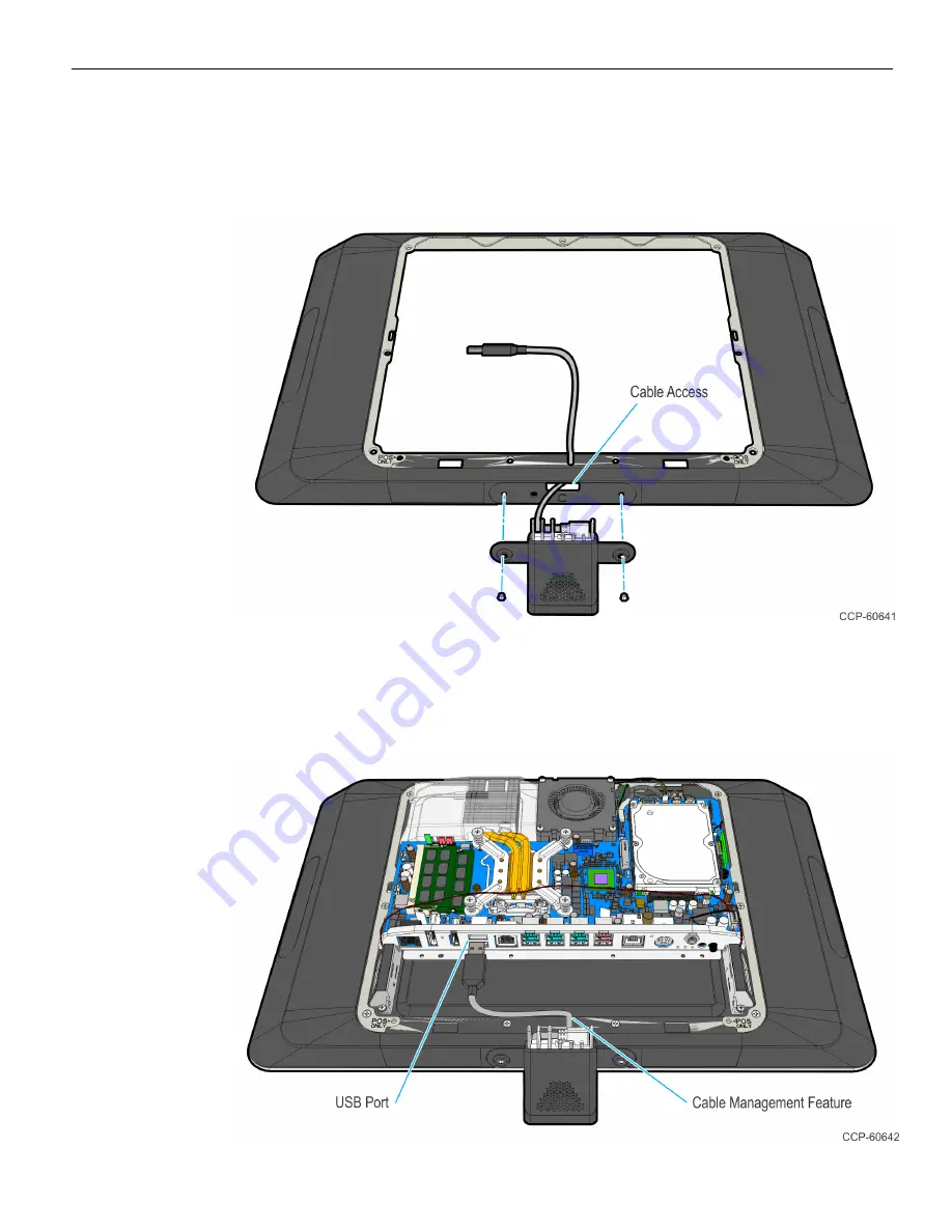
7. Mount the Imaging Scanner on the Display Collar.

a. Route the USB cable through the cable access of the Display Collar.

b. Screw the mounting bracket with the Imaging Scanner onto Port C of the

Display Collar (2 screws).

8. Reinstall the Display Collar.

a. Route the cable onto the cable management feature of the collar.

b. Install the Display Collar onto the terminal (9 screws).

c. Connect the Type A end of the USB cable to the Motherboard.

Содержание 7702-K165

Страница 1: ...KIT INSTRUCTIONS Imaging Scanner 7702 K165 Issue A...

Страница 2: ...eement you have with NCR NCR s copyright notice must be included It is the policy of NCR Corporation NCR to improve products as new technology components software and firmware become available NCR the...

Страница 3: ...Imaging Scanner This kit contains the components to add an Imaging Scanner to the 18 5 or 21 5 display of the RealPOS XR7 POS Kit Contents...

Страница 4: ...izontally or vertically Landscape Configuration 1 Lay the terminal face down on a flat surface Caution Always use a soft material cloth foam to protect the display screen when placing the terminal fac...

Страница 5: ...Remove the Display Collar 9 screws 4 Remove the Blank Plate from Port C of the Display Collar The plate is connected to the Display Collar with a strong adhesive Use care when removing it to not damag...

Страница 6: ...ng Scanner 5 Screw the landscape mounting bracket on the Imaging Scanner 3 screws 6 Connect the Right Angled Micro B end of the USB Cable to the Imaging Scanner and route the cable through the strain...

Страница 7: ...splay Collar b Screw the mounting bracket with the Imaging Scanner onto Port C of the Display Collar 2 screws 8 Reinstall the Display Collar a Route the cable onto the cable management feature of the...

Страница 8: ...terminal face down on a flat surface Caution Always use a soft material cloth foam to protect the display screen when placing the terminal face down 2 Remove the Rear Cover a Loosen the captive screw...

Страница 9: ...Remove the Display Collar 9 screws 4 Remove the Blank Plate from Port B of the Display Collar The plate is connected to the Display Collar with a strong adhesive Use care when removing it to not damag...

Страница 10: ...ng Scanner 5 Screw the portrait mounting bracket on the Imaging Scanner 3 screws 6 Connect the Right Angled Micro B end of the USB cable to the Imaging Scanner and route the cable through the strain r...

Страница 11: ...er 9 7 Mount the Imaging Scanner on the Display Collar a Route the USB cable through the cable access of the Display Collar b Screw the mounting bracket with the Imaging Scanner onto Port B of the col...

Страница 12: ...ollar Secure the cable with tape Note Route the cable as straight as possible between the cable access and the cable management feature to avoid interference when reinstalling the display collar 9 Rei...

Страница 13: ...Imaging Scanner 11 b Connect the 5 POS end of the USB cable to the Motherboard Tuck excess cable length along the sides of the board 10 Replace the Rear Cover on the terminal...

Страница 14: ...12...

Отзывы: