Ametek Land LSP Ex System, User Manual
The Ametek Land LSP Ex System is a cutting-edge industrial monitoring solution. Ensure optimal performance and compliance by downloading the free User Manual from our website. This comprehensive manual provides step-by-step instructions and crucial information for operating the LSP Ex System effectively.
Share
Download


Reviews:
No comments
Related manuals for Land LSP Ex System

ToughRunners
Brand: Baracoda Pages: 2

ScanWear
Brand: Baracoda Pages: 2

RoadRunner BRR-FS
Brand: Baracoda Pages: 2

IDBlue
Brand: Baracoda Pages: 47

RoadRunners Laser
Brand: Baracoda Pages: 12

D-Fly
Brand: Baracoda Pages: 5

RealScan 7892
Brand: NCR Pages: 38

62120
Brand: CEN-TECH Pages: 40

eScan Series
Brand: Plustek Pages: 84

Scanny 7
Brand: Portronics Pages: 2

3R-FS1400TVWT
Brand: 3R Pages: 85

Z-6182
Brand: Zebex Pages: 2

Paragon 1200A3Pro
Brand: Mustek Pages: 38

PageExpress 4800 Pro
Brand: Mustek Pages: 58

FS 500
Brand: MAGINON Pages: 28

Perfecta STP Series
Brand: VARIOUEST Pages: 8

Magellan 9300i
Brand: Datalogic Pages: 520
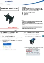
RG760
Brand: Unitech Pages: 2


