80
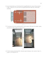
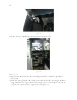
Figure 142
4)
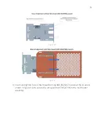
Identify the vacant end along the top rail (top left or top right; whichever side the
OPTIC power supplies do not reside).
Caution: Do not proceed with the installation of the kit if another component is
installed opposite of the OPTIC power supply where the heater is supposed to be
installed. Contact customer service.
5)
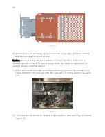
Orient and mount the heater assembly as shown using one of the provided 6-32
screws (006-8611215) and nuts (006-8611426) with nut on the bottom. See Figure
143.
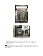
Figure 143
6)
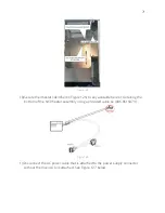
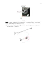
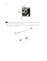
The screw and nut should be installed at the locations called out in Figure 144 and
Figure 145.
Содержание 6003-K001-V002
Страница 2: ......
Страница 4: ......
Страница 18: ...4 RECOMMENDED MATERIALS N A...
Страница 36: ...22 Figure 33 Figure 34...
Страница 44: ...30 Figure 49...
Страница 67: ...53 Figure 92 47 Repeat steps 45 and 46 for the B side of the dispenser...
Страница 102: ...88 Figure 158 5 Replace Lower door using GCBO Lower Door Key See Figure 159 and Figure 160 Figure 159...
Страница 103: ...89 Figure 160...
Страница 110: ...96 Figure 173...
Страница 120: ...106 15 Use a 751 key to close the bottom printer door...
Страница 126: ...112 Figure 200 Figure 201 14 Position heater along bottom dispenser wall like shown See Figure 202 below Figure 202...
Страница 141: ...127 Figure 230 44 Repeat steps 32 43 for the opposite side of the dispenser...
Страница 162: ...148 Figure 270 41 Repeat steps 29 40 for the opposite side of the dispenser...
Страница 163: ...1 MERLIN REVISION B...


