3. RECEIVER
Compact-V
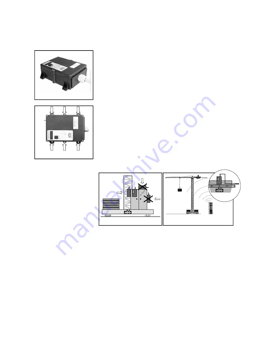
Mounting possibility of the receiver
Compact-V.
.
WRONG
Mounting on a tower slewing crane.
Top slewing crane: Mount the antenna with
extension cable horizontally.
RIGHT
The receiver is connected to the unit to be controlled with the multi-pin connecting
cable supplied. Please observe the instructions issued by the manufacturer of the unit
to be controlled!
The power supply of the receiver is generally effected by the connecting cable.
We recommend urgently to realize this connection via a central, well
accessible, multi-pin plug connector (for example HTS-plug connector series
HE/HB/HN/HA or comparable ones of other manufacturers) to make possible a quick
and clear fault diagnosis in the service case and to take off the receiver without an
expenditure of assembly.
In general, an earth lead is required in case the units to be controlled have not pre-
viously been operated by radio control. Failing this, the
receiver electronic circuit will not receive any power supply. Ensure that the opera-
ting voltage of the receiver
complies with the electrical specifications of
the unit to be controlled. The applicable operating voltage is specified in the supp-
lement.
Never expose the receiver to a high pressure cleaning jet. This applies to the
transmitter also.
The receiver should always be fixed vertically at the outside panel of the swit-
ching cabinet. (The antenna should always reach over the top of the panel.)
You have to make sure that the antenna is not shielded by metal parts totally or part-
ly.
Mounting the receiver in a cabine or in a switching cabinet the antenna should be
layed with an extension cable to the outside and be attached with the fastening
strapping as horizontally as possible with distance to the shielding metal parts.
In general the antenna should always be mounted in such a way so that the antenna
is still visible with each change of position of the transmitter.
%
%
%
%
%
%
WRONG
RIGHT
Compact-V


