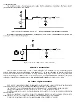
Buzzer without built-in generator can be connected only to OUT1, because only this line has opportunity to modulate
the control signal for the buzzer.
Buzzer with built-in generator can be connected to any output. Connection diagrams for buzzer with build-in
generator and for buzzer without build-in generator have no difference.
14
7
13
6
12
5
11
4
10
3
9
8
2
1
Fuse
(1А)
«GND»
«+»
«-»
Car battery
Buzzer
-
+
Figure 25. Connection diagram of buzzer
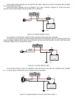
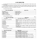
It is possible to connect LED for indication of device operation mode and security mode state.
If the power source is vehicle’s on-board network, the LED must be connected through current-limiting resistor. Such
resistor is already installed inside the lamp in the automotive LED lamps. It is only necessary to select the LED lamp under
the desired voltage of the on-board vehicle network.
14
7
13
6
12
5
11
4
10
3
9
8
2
1
Fuse
(1А)
«GND»
«+»
«-»
Car battery
1-2 kOhm
+
-
LED
Figure 26. Connection diagram of LED
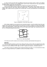
When security functions are used, it is possible to control the car siren. If the siren has a separate input, controlled
by “-”, then the output of the terminal can be connected to this input directly.
14
7
13
6
12
5
11
4
10
3
9
8
2
1
Fuse
(1А)
«GND»
«+»
«-»
Car battery
+
-
IN
Siren
Figure 27. Connection diagram for car siren with control input by “-”.
Содержание SMART S-2420
Страница 11: ...Figure 11 Figure 12...


