NAVTELECOM SMART S-2420 Скачать руководство пользователя страница 17


or calculate the pulses.  

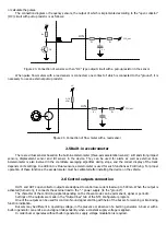
The connection diagram or frequency sensors, the output of which is implemented according to the “open collector” 

(OC) circuit with pull-up resistor is as follows: 


CPU_adc 

R

1

R

2

UIN

C

1

Q2

R

p

+U


Figure 23. Connection of sensors with an “OC” type output circuit with a pull-up resistor in the sensor 


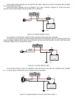
When pulse flow meters with a reed sensor is connected, one contact of which is connected to the “ground”, it is 

necessary to use an external pull-up resistor. 


CPU_adc 

R

1

R

2

UIN

C

1

2–10

кОм

+U


Figure 24. Connection of flow meter with a reed sensor 


2.5 Built-in accelerometer 


There are virtual sensors based on the built-in accelerometer (three-axis acceleration sensor): soft and strong impact 

sensors,  displacement  sensor  and  tilt  sensor  in  the  device.  They  can  be  used  for  alerts  as  well  as  external  lines. 

Accelerometer is also involved in the coordinate averaging algorithm during stops, and the correct display of the track 

depends on its settings. In addition to virtual sensors, accelerometer is used for such functions as EcoDriving. For proper 
operation of these functions, the accelerometer must be calibrated after installing the device on the vehicle. 


2.6 Control outputs connection 

 
OUT1 and OUT2 open collector outputs are designed to control low-current loads up to 500 mA. When the output is 

activated (turned on), it connects the external load to the "-" power supply (to the "ground"). 

The character of the controlling signal depending on the chosen mode can be permanent, signal or periodic.  

Settings of the outputs are made in the “Output lines” tab of the NTC Configurator program.  

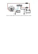
One of the outputs can be used for control of sound signal emitting with help of the buzzer, for warning or EcoDriving 

function indication. 

Buzzers may be different in operating voltage, in the presence or absence of a built-in generator. A buzzer with a 

built-in generator can emit a sound signal independently when a constant supply voltage is applied. 

In order buzzer operates without built-in generator, supply voltage modulation is required.  

Содержание SMART S-2420

Страница 1: ...GPS GLONASS TRACKING EQUIPMENT SMART S 2420 Operations manual Installation and connection of the device v1 0 MOSCOW 2020...

Страница 2: ...terested in constantly improvement of the manufactured products quality Please contact our technical support by email address support navtelecom ru should you have any questions or problems with the d...

Страница 3: ...et 7 1 7 Device components 9 1 8 Device interface connector 11 2 CONNECTION OF THE DEVICE 12 2 1 Installation 12 2 2 SIM card installation and operation 13 2 3 Power connection 13 2 4 Universal inputs...

Страница 4: ...passenger s safety 1 3 Operational principles The device during its operation continuously monitors the status of the connected sensors vehicle battery voltage GSM modem signal level operational capa...

Страница 5: ...7 Current consumption at 12 V voltage in operation mode on Average2 mA 80 Current consumption at 12 V voltage with turned off GLONASS and GSM modules is no more than mA 20 Maximum current consumption...

Страница 6: ...voltage is exceeded the power protection is activated The device continues to work but is powered by the battery 2 If GPRS operates in poor communications peak consumption 10 ms consumption of the de...

Страница 7: ...iniUSB connector for connection with a computer SIM card holder slot with ejector yellow button In the upper part of the device unit figure 3 there are three indicators system indicator SYS modem oper...

Страница 8: ...res 1 4 Interface cable with MiniUSB connector 1 5 Passport 1 6 Package 1 Figure 4 14 pin connector of Microfit 14 Figure 5 Interface cable with MiniUSB connector Some cases may require connection of...

Страница 9: ...gure 7 Fuel level sensor Figure 8 External LED The manufacturer reserves the right to complete the devices with equipment whose set appearance and characteristics differ from those shown in the figure...

Страница 10: ...res 9 12 1 front cover 2 fixing hole 3 system LED indicator 4 GSM LED indicator 5 GLONASS GPS LED indicator 6 14 pin connector 7 MiniUSB connector 8 SIM card 1 ejector holder 9 SIM card holder 1 exter...

Страница 11: ...Figure 11 Figure 12...

Страница 12: ...ency It allows to connect to them a wide range of different sensors for example frequency frequency from 1 Hz to 2000 Hz and analog voltage from 0 V to 31 V FLS impulse fuel consumption sensors DRL bu...

Страница 13: ...places with an ambient temperature more than 60 C for example near heating systems etc It is also prohibited to place the device in a sealed container without heat dissipation It is prohibited to inst...

Страница 14: ...chnical characteristics When voltage surges which is more than the specified ratings occur the built in overvoltage protection system will operate in the device It is strongly recommended to connect t...

Страница 15: ...measurement event become available CPU_adc R1 R2 UIN C1 U Figure 14 Connection of analog sensors 2 4 2 Discrete sensors connection The device allows to connect any type of sensors that have two stead...

Страница 16: ...algorithms for example when they are averaged at parking lots energy saving when calculating engine hours and in some other device algorithms Any input which configured for operation with a discrete...

Страница 17: ...lay of the track depends on its settings In addition to virtual sensors accelerometer is used for such functions as EcoDriving For proper operation of these functions the accelerometer must be calibra...

Страница 18: ...e If the power source is vehicle s on board network the LED must be connected through current limiting resistor Such resistor is already installed inside the lamp in the automotive LED lamps It is onl...

Страница 19: ...contacts are always marked as 30 87 and 87a The 30th pin is always in the relay Without applying voltage to the winding contacts it is permanently closed to contact 87a If a signal is applied to the...

Страница 20: ...30 85 86 87a 87 14 7 13 6 12 5 11 4 10 3 9 8 2 1 Fuse 1A GND Car battery Diode 1N4007 Fuse External device GND Figure 30 Connection diagram of the relay to the outputs of the device OUT1 and OUT2...

Страница 21: ...cond off There is a registration in the cellular network of the operator Weak signal 2 short flashes 1 second off There is a registration in the cellular network of the operator Medium quality signal...

Отзывы: