background image


 Version 21.10.2022 

HW: 25(V21) 

RL2-LR14 

P

a

g

e

6


2.


Installation 


To install the interface, first switch off the ignition and disconnect the vehicle’s battery. 
Please read the owner`s manual of the car, regarding the battery`s disconnection! If 
required, enable the car`s Sleep-mode (hibernation mode)  
In case the sleep-mode does not succeed, the disconnection of the battery can be done 
with a resistor lead. 
If the necessary stabilized power supply for the interface is not taken directly from the 
battery, the chosen connection has to be checked for being constantly stabile.  
The interface needs a permanent 12V source!


2.1.


Place of installation 

 
The interface is supposed to be installed at a suitable location behind the vehicle`s head-
unit.  


Содержание RL2-LR14

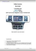
Страница 1: ...ion 3 infotainment Video inserter for rear view camera Product features Video inserter for factory infotainment systems 1 CVBS Input for rear view camera Automatic switching to rear view camera input...

Страница 2: ...ace 1 4 Settings 4 Dip switches 2 Installation 2 1 Place of installation 2 2 Connection schema 2 3 Connection picture signal cable 2 4 Connection 10pin Power CAN cable 2 5 After market rear view camer...

Страница 3: ...ffer free software updates for our interfaces To receive a free update the interface has to be sent in at own cost Wages for de and reinstallation and other expenditures involved with the software upd...

Страница 4: ...over Evoque L538 Range Rover Sport L320 Discovery4 L319 model years 2012 2014 Range Rover Vogue L322 Freelander2 L359 model years 2013 Only for vehicles with automatic gear shift vehicles model years...

Страница 5: ...ds the vehicle s digital signals out of the vehicle s CAN bus and converts them for the video interface 1 4 Settings of the 4 Dip switches The 4 dip switches of the video are used to select the kind a...

Страница 6: ...eep mode hibernation mode In case the sleep mode does not succeed the disconnection of the battery can be done with a resistor lead If the necessary stabilized power supply for the interface is not ta...

Страница 7: ...Version 21 10 2022 HW 25 V21 RL2 LR14 Page 7 2 2 Connection schema...

Страница 8: ...era to the video input connector of the video interface Connect the yellow cinch connector of the enclosed video output cable to the video output connector of the video interface Connect the opposite...

Страница 9: ...he 10pin PNP power CAN cable s male 16pin connector Connect the 10pin PNP power CAN cable s opposite female 16pin connector to the previously become free 16pin connector of the head unit Connect the 1...

Страница 10: ...rse OUT of the 10pin PNP Power CAN cable while reverse gear is engaged the video interface will automatically switch to the rear view camera input IN while the reverse gear is engaged If the video int...

Страница 11: ...function Connect the Reverse light s power cable to coil 85 and the vehicle s ground to coil 86 of the relay Connect the output connector 87 of the relay to the rear view camera s power cable like you...

Страница 12: ...monitor Note The OSD menu is only shown when a working video source is connected to the rear view camera input of the interface The following settings are available Brightness Saturation Position H ho...

Страница 13: ...ensions video box 80 x 22 x 110 mm W x H x D 4 Technical Support Please note that direct technical support is only available for products purchased directly from NavLinkz GmbH For products bought from...

Отзывы: