background image


4 | 

P a g e


Agreement

End user agrees to use this product in compliance with all State and Federal laws. NAV-TV Corp. would not be held liable for misuse of its product. If you do 

not agree, please discontinue use immediately and return product to place of purchase. This product is intended for off-road use and passenger entertainment only.


DO NOT GRAB POWER & GROUND (FOR CAMERA) FROM THE REVERSE LIGHT. 

For all installations, the power, ground and CAN wires from the UCT-13 module must be soldered behind the radio screen at 
the main connector. Refer to page 3 for diagrams.  

If using an AVSW (Nav-TV switcher) and the vehicle has a factory reverse camera, you must cut the DIFF camera signal wires 
in half behind the screen, and solder on RCAs from both pair of ends to be plugged into the AVSW (page 6 & 7).  

When adding an aftermarket camera: power, ground and signals can be grabbed at the tailgate connector (inside the 
tailgate, behind the handle). The wires are as follows: 

-

Black:

 Ground 


-

Pink/Yellow:

  12v Ignition 


-Green/Brown:

 Differential Video (-): Connect this wire to the camera’s 

RCA Signal, at the tailgate only

.* 


-Green/Orange:

 Differential Video (+): Connect this wire to the camera’s 

RCA Shield, at the tailgate only

.* 

*Note:

 the above Diff video signal connections appear to be backwards, but they are accurate. Connecting them any other 

way will distort the image.  


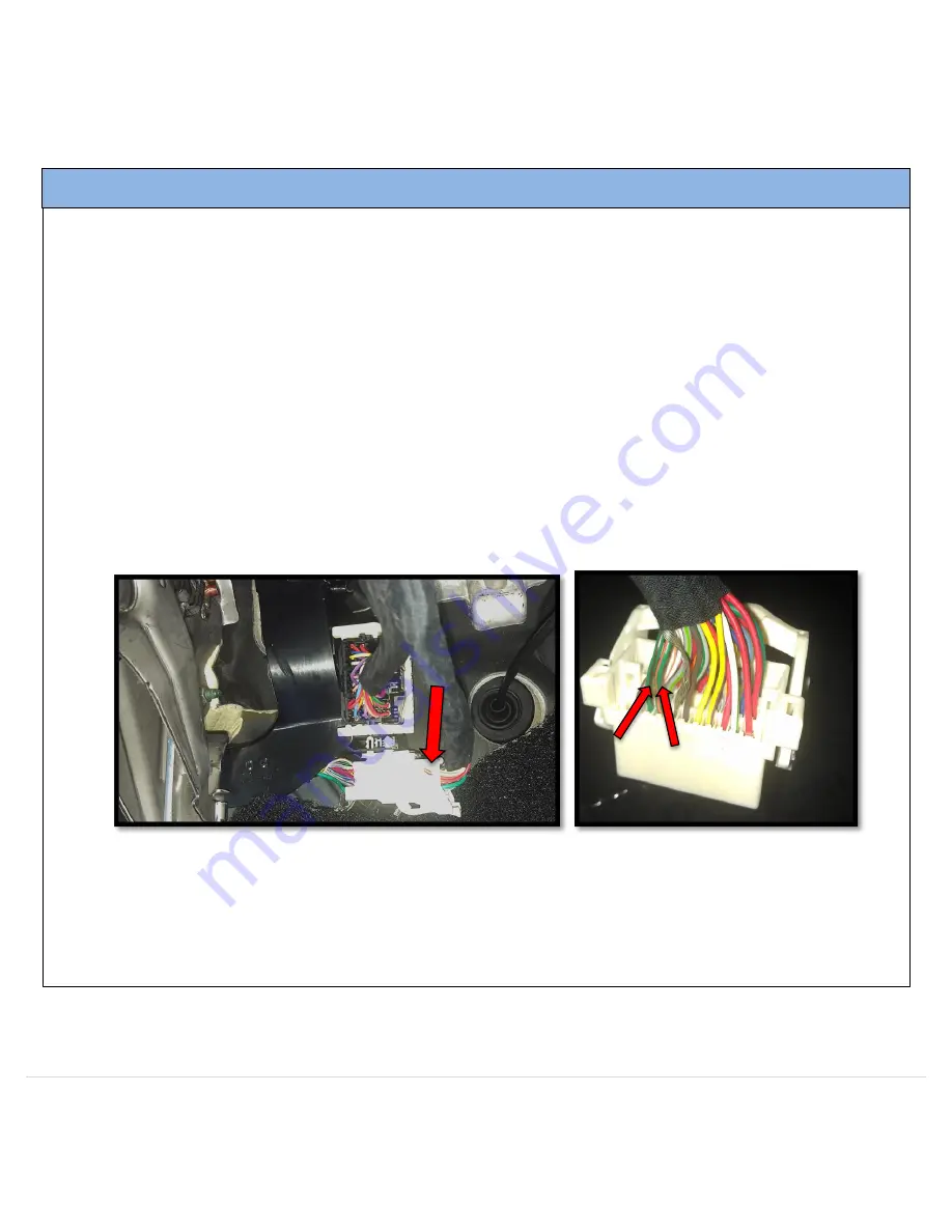
 Differential video signal wires (same as those found in the tailgate connector) can be picked up in the drivers kick panel in 
the following connector, to expedite install time: 


Cut an RCA cable (keep the male end); leave enough length to run from the drivers kick up into the dash behind the radio. 
Solder the cut end of the RCA cable to the green/orange (Shield) and green/brown (Signal) wires in the kick panel. Connect 
the RCA to the UCT-13’s supplied RCA that you’ve populated behind the radio.  

If installing an external AV source, the audio connections must be made at the factory AUX input, in the center console. 

Solder ALL connections! 


Installation tips 

Содержание UCT-13

Страница 1: ...Brendon Martell February 5 2013 Nav TV UCT 13 Dodge UConnect Camera Interface...

Страница 2: ...f you do not agree please discontinue use immediately and return product to place of purchase This product is intended for off road use and passenger entertainment only Included Parts Needed Tools Tor...

Страница 3: ...F CAM is activated AVSW V2 Trigger 13 AVSW 8 RCA Female Normally Open 15 RCA Female Normally Closed 16 Brown CAN LOW Radio 17 RAM 12 Radio side Blue CAN LOW Vehicle 18 RAM 12 Vehicle side 13 Dodge Ra...

Страница 4: ...r inside the tailgate behind the handle The wires are as follows Black Ground Pink Yellow 12v Ignition Green Brown Differential Video Connect this wire to the camera s RCA Signal at the tailgate only...

Страница 5: ...ee please discontinue use immediately and return product to place of purchase This product is intended for off road use and passenger entertainment only Female RCA cable for camera input must be popul...

Страница 6: ...y and return product to place of purchase This product is intended for off road use and passenger entertainment only Garmin NTX54 and Stand Alone module sold separately AVSW audio ports are not used O...

Страница 7: ...In order to save setting changes made in Nav TV programming mode you must scroll until you see EXIT on the cluster and press enter with the tuning knob or press the BACK button Don t forget to check o...

Страница 8: ...for 2 seconds To exit forced front camera press and release radio BACK radio Activate NAV mode To activate the NAV screen press and hold radio SCREEN OFF button for 2 seconds To exit NAV mode press a...

Страница 9: ...rchase This product is intended for off road use and passenger entertainment only Dodge Ram Radio removal 4 Remove the Torx 20 screw at the rear of the pocket on the right side of the dash Remove 2 mo...

Страница 10: ...the MUTE button until you see the display options post on the cluster Q2 I m getting no image at all on my factory screen A2 Verify your connections are correct starting with the CAN data wires Also c...

Отзывы: