


Page 3-4
ATU-HP Technical Instruction Manual
Issue 2.0
Section 3 Operating Instructions
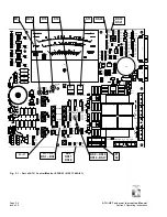
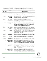
Table 3-1: ATU Control/Monitor PWB Controls and Indicators
(Continued)
REF DES
PANEL
MARKING
DESCRIPTION
A1DS13
R TUNING –
INCREASE
When turned on (amber), indicates that the ATU-HP is
attempting to tune by increasing the variable matching
transformer’s input resistance.
A1DS14
R TUNING –
NORMAL
When turned on (green), indicates that the ATU-HP’s variable
matching transformer is properly tuned.
A1DS15
R TUNING –
DECREASE
When turned on (amber), indicates that the ATU-HP is
attempting to tune by decreasing the variable matching
transformer’s input resistance.
A1DS16
R TUNING – MIN
LIMIT
When turned on (red), indicates that the ATU-HP reached a
minimum resistive matching limit while attempting to tune by
decreasing the input resistance. The motor will be inhibited
from causing further resistive match decrease.
A1DS17
R TUNING –
INHIBIT
When turned on (red), indicates that the ATU-HP’s automatic
resistive tuning has been inhibited by pressing the
R TUNING
– INHIBIT
switch (A1S7) or via remote control.
A1DS18
+12V-B
When turned on (green), indicates the +12 V-B regulated low
voltage power supply, which supplies the resistive tuning
control circuitry, is present.
A1DS19
FAN FAIL 1
When turned on (red), indicates cooling fan 1 (B2) has failed.
A1DS20
CPU OK
When flashing (green), indicates the ATU control/monitor
PWB’s microcontroller is functional.
A1DS21
FAN FAIL 2
When turned on (red), indicates cooling fan 2 (B3) has failed.
A1-A
Reflected Power
Meter Scale
Wire jumper that determines the reflected power scale to
read on meter A1M1. Jumper connects to screw terminal E1
for the 0 - 400 W scale. Jumper connects to screw terminal
E2 for the 0 - 120 W scale.
A1-B
Forward Power
Meter Scale
Wire jumper that determines the forward power scale to read
on meter A1M1. Jumper connects to screw terminal E3 for
the 0 - 4000 W scale. Jumper connects to screw terminal E4
for the 0 - 1200 W scale.
A1-C
Antenna Current
Meter Scale
Wire jumper that determines the antenna current scale to
read on meter A1M1. Jumper connects to screw terminal E5
for the 0 -10 A scale. Jumper connects to screw terminal E6
for the 0 – 30 A scale.


