ATU-HP Technical Instruction Manual
Page 3-1
Section 3 Operating Instructions
Issue 2.0
ATU-HP
TECHNICAL INSTRUCTION MANUAL
Section 3
OPERATING INSTRUCTIONS
3.1 INTRODUCTION
This section provides the information required
to place the ATU-HP in operation. The
ATU-HP will normally be unattended during
use. The following instructions are intended
for persons involved in testing or
maintenance of the equipment.
WARNING
Use extreme caution near the tuning
coils. Extremely high RF voltages, that
may arc many inches of air breakdown
path
and cause severe RF burns, are
present when an RF input of any level is
applied to the ATU-HP.
3.2 EMERGENCY SHUTDOWN
There are no special procedures to be
observed if an emergency shutdown is
required. Remove RF input by having
transmitter's RF output turned off or by
disconnecting RF input coaxial cable from RF
input connector J3.
3.3 CONTROLS AND INDICATORS
All of the controls and indicators for the
automatic antenna tuning unit are located on
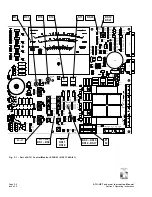
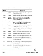
the ATU control/monitor PWB (A1). Figure
3-1 and Table 3-1 identify and describe the
controls and/or indicators on the ATU
control/monitor PWB. It is recommended the
operator/maintainer be familiar with the ATU
controls and indicators before placing the
ATU-HP into service and/or attempting to
perform fault diagnostics.
NOTE
On some assembly detail drawings,
numbered callouts are provided to cross-
reference the control/indicator to the
description table.
The names used in the PANEL MARKING
column of the controls and indicators tables
are intended to be the closest possible
representation to the item’s label/silkscreen.
.


