


Stage 3 of Tuning Procedure
Final Setting of L and R Tuning Taps (
LOCAL
control,
TUNE SETUP
off)
ATU-HP Technical Instruction Manual
Page 2-17
Section 2 Preparation for Use and Installation
Issue 2.0
Paragraph 2.5 continued
Table 2-4:
Determining ‘R Match’
Freq.
(kHz)
R Match
(
Ω
)
Freq.
(kHz)
R Match
(
Ω
)
190 16.9 370 64.2
200 18.8 380 67.7
210 20.7 390 71.4
220 22.7 400 75.1
230 24.8 410 78.9
240 27.0 420 82.8
250 29.3 430 86.7
260 31.7 440 90.8
270 34.2 450 95.0
280 36.8 460 99.3
290 39.5 470 103.6
300 42.2 480 108.1
310 45.1 490 112.6
320 48.0 500 117.3
330 51.1 510 122.0
340 54.2 520 126.9
350 57.5 530 131.8
360 60.8 535 134.3
(o) Divide the ‘R match’ value from step
(n) by the antenna resistance from
step (k) (from Table
2-3
). For
example, if R match = 48.0
Ω
and
antenna resistance = 4
Ω
, the
resistance ratio will be 12.0.
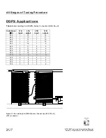
(p) Enter the resistance ratio from step (o)
into Table 2-5 (or closest possible
option) to determine the input (green
wire) and output (red wire) taps for T1.
(q) Connect the green T1-Input (
IN
) wire
and the red T1-Output (
OUT
) wire to
the taps determined in step (p).
(r) Turn on the transmitter and allow
sufficient time for the loading coils and
the variable resistive matcher to tune.
WARNING
Ensure the transmitter is off when
making adjustments on the ATU-HP.
Lethal voltages are present when any
level of RF is applied to the ATU-HP.
Table 2-5:
T1 Taps vs Resistance
Ratio
T1 Taps IN
OUT
6 5 4 3
5
1.31
- - -
4
1.78 1.36 -
-
3
2.56 1.96 1.44 1.0
2
4 3.06 2.25 1.56
9
7.11
5.44 - 2.78
8
16 12.25 9 6.25
7
64 49 36 25
(s) If an
L TUNING – MAX LIMIT
or
MIN
LIMIT
LED turns on, turn off the
transmitter and tap the tuning coils for
the next closest inductance value in
the appropriate Table 2-6 a-f. Use the
next
higher
inductance value for a
MAX LIMIT
indication and the next
lower
inductance value for a
MIN
LIMIT
indication respectively.
(t) If
an
R TUNING – MAX LIMIT
or
MIN
LIMIT
LED turns on, turn off the
transmitter and tap for the next closest
resistance ratio in Table 2-5. Use the
next
lower
resistance ratio tap for a
MAX LIMIT
indication and the next
higher
resistance ratio for a
MIN
LIMIT
indication. Repeat step (r).
(u) When no
L TUNING
or
R TUNING –
MAX LIMIT
or
MIN LIMIT
LEDs occur,
the ATU-HP is tuned. The
NORMAL
LEDs should turn on.
(v) Check the position of the variometer
inside the bottom of loading coil L1A,
noting it is behind the ATU-HP’s
protective cover, which also supports
the ATU control/monitor PWB.
WARNING
Ensure the transmitter is off when
making adjustments on the ATU-HP.
Lethal voltages are present when any
level of RF is applied to the ATU-HP.


