PCB Layout
www.ti.com
16
SLVUAY0 – November 2016
Submit Documentation Feedback
Copyright © 2016, Texas Instruments Incorporated
TPS65132S Evaluation Module
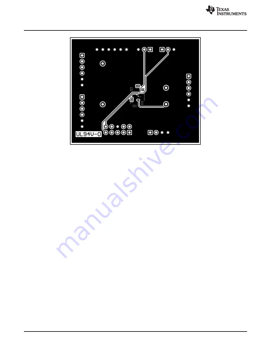
Figure 19. PCB Bottom Layer (Bottom View)
Страница 1: ...Points 5 5 Setup 6 6 Software Operation 9 7 PCB Layout 14 8 List of Materials 17 List of Figures 1 Schematic 4 2 Hardware Setup Full Functionality 6 3 Hardware Setup Simplified 6 4 Two Terminal Power...
Страница 2: ...t and output voltage sense terminals for making accurate four terminal voltage measurements 1 1 Recommended Equipment In addition to the contents of the EVM box some or all of the equipment described...
Страница 3: ...the TPS65132S EVM 1 IO means that the load is connected from VPOS to VNEG Table 1 Electrical Specifications Parameter Notes and Conditions MIN TYP MAX Unit Input Characteristics VIN Input voltage 2 5...
Страница 4: ...1 2 3 JP2 1 2 3 JP1 AGND D2 CFLY1 C3 CFLY2 A3 SYNC A1 EN B1 OUTP E3 OUTN A2 PGND B3 PGND E1 REG D3 REG E2 SCL B2 SDA C2 SW D1 VIN C1 U1 TPS65132SYFF CFLY2 4 7 F C2 10 F C3 10 F C5 2 2 H L1 Copyright 2...
Страница 5: ...he negative output and ground Figure 6 or between the positive and negative outputs Figure 7 S 3 Negative Output Sense GND 4 5 6 Ground J4 I2 C Bus SCL 9 Clock Use the 10 way ribbon cable supplied wit...
Страница 6: ...o any other configuration settings are needed use the simplified set up shown in Figure 3 If using the simplified setup the TPS65132S device starts up with the register settings stored in its EEPROM t...
Страница 7: ...dback Copyright 2016 Texas Instruments Incorporated TPS65132S Evaluation Module Figure 4 Two Terminal Power Supply Connection W H I T E S P A C E Figure 5 Four Terminal Power Supply Connection W H I T...
Страница 8: ...ee Figure 2 To download the latest version of the EVM software Go to the TPS65132 product folder on the TI Web site http www ti com product tps65132 toolssoftware Download the software zip file Unzip...
Страница 9: ...arts select the device you want to evaluate from the drop down menu and then click on OK refer to Figure 9 W H I T E S P A C E Figure 9 Device Selection Window After selecting the device variant and c...
Страница 10: ...the pullup resistors if they are not needed Check the Pullups checkbox if using the I2 C pullup resistors in the USB2ANY interface adapter refer to Figure 11 This is the most common setting Uncheck th...
Страница 11: ...age or hexadecimal entry boxes the software rounds that entry down to the nearest correct value If a value below the minimum output voltage is entered the software uses the minimum value Use the Vpos...
Страница 12: ...which data the window shows Click on Write to program the registers in the TPS65132S device with the contents shown in the GUI window Click on Write Modified to program only the selected register in t...
Страница 13: ...software when one of the previous conditions is true an error message like the one shown in Figure 14 displays Clicking on Continue in Demo Mode operates the software as if an EVM were connected but...
Страница 14: ...ircuit board PCB The EVM has been designed using a four layer 35 m 1 oz copper clad circuit board All components are on the top side and all signal traces on the top and bottom layers allow the user t...
Страница 15: ...CB Layout 15 SLVUAY0 November 2016 Submit Documentation Feedback Copyright 2016 Texas Instruments Incorporated TPS65132S Evaluation Module Figure 17 PCB Inner Layer 1 Top View Figure 18 PCB Inner Laye...
Страница 16: ...PCB Layout www ti com 16 SLVUAY0 November 2016 Submit Documentation Feedback Copyright 2016 Texas Instruments Incorporated TPS65132S Evaluation Module Figure 19 PCB Bottom Layer Bottom View...
Страница 17: ...age Reference Part Number Manufacturer C1 C2 C4 3 4 7uF CAP CERM 4 7 F 16 V 10 X5R 0603 0603 GRM188R61C475KAAJ Murata C3 1 10uF CAP CERM 10 F 25 V 20 X5R 0603 0603 GRM188R61E106MA73D Murata C5 1 10uF...
Страница 18: ...are returned during the warranty period to the address designated by TI and that are determined by TI not to conform to such warranty If TI elects to repair or replace such EVM TI shall have a reasona...
Страница 19: ...transmitter has been approved by Industry Canada to operate with the antenna types listed in the user guide with the maximum permissible gain and required antenna impedance for each antenna type indic...
Страница 20: ...ified allowable ranges some circuit components may have elevated case temperatures These components include but are not limited to linear regulators switching transistors pass transistors current sens...
Страница 21: ...REMOVAL OR REINSTALLATION ANCILLARY COSTS TO THE PROCUREMENT OF SUBSTITUTE GOODS OR SERVICES RETESTING OUTSIDE COMPUTER TIME LABOR COSTS LOSS OF GOODWILL LOSS OF PROFITS LOSS OF SAVINGS LOSS OF USE L...
Страница 22: ...sponsible for compliance with all legal regulatory and safety related requirements concerning its products and any use of TI components in its applications notwithstanding any applications related inf...