©
National Instruments Corporation
25
NI UMI-7774/72 User Guide and Specifications
Closed-loop servo applications require consistent directional polarity between the motor and encoder
for correct operation. The National Instruments motion control standard directional polarity is as
follows:
•
Positive = forward = clockwise (CW) facing motor shaft
•
Negative = reverse = counterclockwise (CCW) facing motor shaft
Caution
Use a shielded cable to prevent noise from corrupting the encoder signals. Noise on the
encoder lines can result in lost counts, reduced accuracy, and other erroneous encoder and motion
controller operations.
When connecting the encoder signals to the UMI-7774/72, use shielded wire of at least 24 AWG.
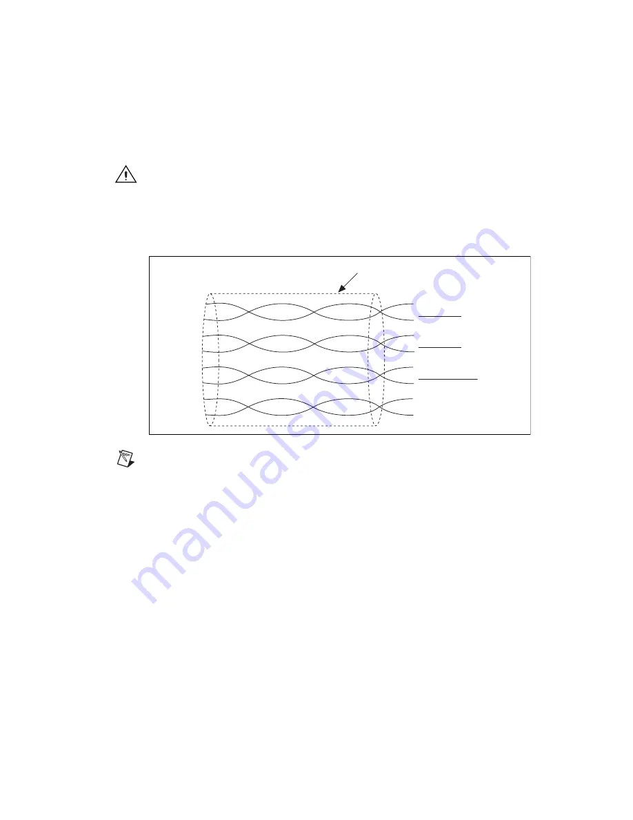
National Instruments recommends you use cables with twisted pairs and an overall shield for improved
noise immunity and signal integrity. Figure 23 shows twisted pairs in a shielded cable.
Figure 23.
Shielded Twisted Pairs
Note
Some drives have pass-through signaling on encoders. If the drive has the pass-through
feature, ensure that the drive does not filter the encoder signals because this could reduce achievable
closed-loop performance and stability for the system. If the drive does not have pass-through
signaling for encoders or if you choose not to use the pass-through signaling, you can connect the
UMI-7774/72 to the encoders directly.
Limit and Home Inputs
The UMI-7774/72 has connections available for forward limit, reverse limit, and home sensors or
switches. The limit sensors or switches are typically located at physical ends of travel. The home sensor
or switch can be located at any reference position within the range of travel.
The limits and home inputs are optically isolated sinking inputs on the UMI-7774/72. A sinking input
is an input terminal that can sink current by providing a path to a supply common or ground. You can
wire this type of input to a sourcing output device. A sourcing output device can source current by
providing a path to a supply source. PNP sensors are examples of sourcing output devices.
To cause current to flow through the input, the voltage applied to the limit and home inputs must be
greater than 3.5 V and less than 30 V. Also, the source must be able to provide at least 7.2 mA to turn
on the optical isolator and result in an ON condition. When the applied voltage is below 2 V, the input
results in an OFF condition.
Encoder A
Encoder A
Encoder B
Encoder B
Encoder Index
Encoder Index
+5 V
Digital Ground
Shield
Drain
Artisan Technology Group - Quality Instrumentation ... Guaranteed | (888) 88-SOURCE | www.artisantg.com


