background image

©

 National Instruments Corporation

v

NI PXI-1036/PXI-1036DC User Manual

Contents

About This Manual

Conventions ...................................................................................................................vii
Related Documentation..................................................................................................viii

Chapter 1
Getting Started

Unpacking ......................................................................................................................1-1
What You Need to Get Started ......................................................................................1-1
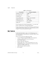
Key Features ..................................................................................................................1-2
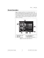
Chassis Description........................................................................................................1-3
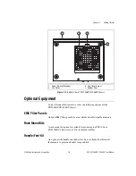
Optional Equipment .......................................................................................................1-5

EMC Filler Panels ...........................................................................................1-5
Rack Mount Kits..............................................................................................1-5
Handle/Feet Kit ...............................................................................................1-5
DC Power Cable (PXI-1036DC Only) ............................................................1-6

PXI-1036/PXI-1036DC Backplane Overview...............................................................1-6

Interoperability with CompactPCI ..................................................................1-6
System Controller Slot ....................................................................................1-7
Star Trigger Slot ..............................................................................................1-7
Peripheral Slots................................................................................................1-7
Local Bus.........................................................................................................1-7
Trigger Bus ......................................................................................................1-8
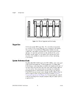
System Reference Clock..................................................................................1-8

Chapter 2
Installation and Configuration

Safety Information .........................................................................................................2-1
Chassis Cooling Considerations ....................................................................................2-2

Providing Adequate Clearance ........................................................................2-2
Setting Fan Speed ............................................................................................2-3
Installing Filler Panels.....................................................................................2-3

Rack Mounting ..............................................................................................................2-4
Connecting Safety Ground.............................................................................................2-4
Connecting to Power Source..........................................................................................2-4

Connecting to an AC Power Source ................................................................2-5
Connecting to a DC Power Source (PXI-1036DC Only)................................2-5

DC Connector ...................................................................................2-5

Installing a PXI Controller.............................................................................................2-6

Содержание PXI-1036DC

Страница 1: ...PXI NI PXI 1036 PXI 1036DC User Manual NI PXI 1036 PXI 1036DC User Manual December 2010 371550E 01...

Страница 2: ...banon 961 0 1 33 28 28 Malaysia 1800 887710 Mexico 01 800 010 0793 Netherlands 31 0 348 433 466 New Zealand 0800 553 322 Norway 47 0 66 90 76 60 Poland 48 22 328 90 10 Portugal 351 210 311 210 Russia...

Страница 3: ...n information retrieval system or translating in whole or in part without the prior written consent of National Instruments Corporation National Instruments respects the intellectual property of other...

Страница 4: ...36DC Backplane Overview 1 6 Interoperability with CompactPCI 1 6 System Controller Slot 1 7 Star Trigger Slot 1 7 Peripheral Slots 1 7 Local Bus 1 7 Trigger Bus 1 8 System Reference Clock 1 8 Chapter...

Страница 5: ...gger Configuration in MAX 2 11 Using System Configuration and Initialization Files 2 12 Chapter 3 Maintenance DC Fuse Replacement PXI 1036DC Only 3 1 Service Interval 3 1 Preparation 3 1 Cleaning 3 2...

Страница 6: ...ata loss or a system crash When this symbol is marked on the product refer to the Read Me First Safety and Electromagnetic Compatibility document shipped with the product for precautions to take bold...

Страница 7: ...NI PXI 1031DC 1036DC DC Cable Kit Installation Guide CompactPCI Specification PICMG 2 0 R 3 0 PXI Hardware Specification PXI Software Specification IEEE 1101 1 1991 IEEE Standard for Mechanical Core S...

Страница 8: ...hardware and switches are undamaged Inspect the inner chassis for any possible damage debris or detached components If damage appears to have been caused during shipment file a claim with the carrier...

Страница 9: ...ty in a wide range of applications The key features of the chassis include the following Accepts 3U PXI and CompactPCI PICMG 2 0 R 3 0 modules 6 slot chassis with universal AC input and automatic volt...

Страница 10: ...xcept for the chassis name stenciled on the face plate Figure 1 2 shows the rear view of the PXI 1036 Figure 1 3 shows the rear panel of the PXI 1036DC Figure 1 4 shows the bottom of the chassis both...

Страница 11: ...PXI 1036DC Chassis 1 Rear Exhaust Vents 2 AC Input 3 Power Supply Fan Exhaust 4 Chassis Ground Screw 5 AUTO HIGH Fan Speed Selector Switch 6 Rubber Foot 1 Rear Exhaust Vents 2 DC Fuse Socket 3 DC Inp...

Страница 12: ...XI 1036DC chassis EMC Filler Panels Optional EMC filler panel kits are available from National Instruments Rack Mount Kits A rack mount kit option is available for mounting the PXI 1036 or PXI 1036DC...

Страница 13: ...nt feature because some PXI systems may require components that do not implement PXI specific features For example you may want to use a standard CompactPCI network interface card in a PXI chassis The...

Страница 14: ...eripheral module in this slot The star trigger slot can also be used to provide a PXI_CLK10 signal to the backplane For more information regarding PXI_CLK10 refer to the System Reference Clock section...

Страница 15: ...PXI 10 MHz system clock signal PXI_CLK10 independently to each peripheral slot An independent buffer having a source impedance matched to the backplane and a skew of less than 250 ps between slots dri...

Страница 16: ...e of this equipment to minimize shock hazards Refer to the Connecting Safety Ground section for instructions on connecting safety ground Live Circuits Operating personnel and service personnel must no...

Страница 17: ...odule cooling Air enters through the fan inlet in the bottom of the chassis for module cooling It then exits through the upper sections at the right side back and through the top as shown in Figure 2...

Страница 18: ...and PXI 1036DC Refer to Figure 1 2 Rear View of the PXI 1036 Chassis or Figure 1 3 Rear View of the PXI 1036DC Chassis to locate the fan speed selector switch Select HIGH for maximum cooling performan...

Страница 19: ...afety ground For DC powered applications or if your power outlet does not have an appropriate ground connection you must connect the premise safety ground to the chassis grounding screw located on the...

Страница 20: ...nnecting to a DC Power Source PXI 1036DC Only For full chassis power the DC source must be capable of providing a minimum of 300 watts of continuous power per feed pair to the P1 connector on the PXI...

Страница 21: ...om National Instruments that incorporates an in line fuse and the mating connector for the P1 port Installing a PXI Controller This section contains general instructions for installing a PXI controlle...

Страница 22: ...as shown in Figure 2 3 Figure 2 3 Injector Ejector Handle Position during Controller or Peripheral Module Insertion 3 When you begin to feel resistance push up on the injector ejector handle to inject...

Страница 23: ...036DC Chassis Installing PXI Modules Complete the following steps to install a module 1 Make sure the power switch is in the Off Standby position 2 Install a module into a chassis slot by first placin...

Страница 24: ...p on the injector ejector handle to fully inject the module into the chassis frame Secure the module front panel to the chassis using the module front panel mounting screws Figure 2 5 Installing PXI o...

Страница 25: ...NI Driver CD ROM the MAX icon will be present on the desktop The configuration steps for single or multiple chassis systems are the same Figure 2 6 Chassis Configuration in MAX Basic PXI System Confi...

Страница 26: ...ger Configuration in MAX Each chassis has one or more trigger buses each with eight lines numbered 0 through 7 that can be reserved and routed statically or dynamically Static reservation pre allocate...

Страница 27: ...e media that comes with the chassis The information in this file is combined with information about the system controller to create a single system initialization file called pxisys ini PXI System Ini...

Страница 28: ...e the fuse pull straight out from the chassis Service Interval Clean dust from the chassis exterior and interior as needed based on the operating environment Periodic cleaning increases reliability Pr...

Страница 29: ...round components Exterior Cleaning Cautions Avoid getting moisture inside the chassis during exterior cleaning especially through the top vents Use just enough moisture to dampen the cloth Do not wash...

Страница 30: ...ns for the PXI 1036 and PXI 1036DC chassis PXI 1036 Chassis Electrical Caution Overloading the circuits may damage supply wiring Do not exceed the ratings on the equipment nameplate when connecting eq...

Страница 31: ...ent protection All outputs protected from short circuit and overload Over voltage protection Chassis Cooling Per slot cooling capacity 25 W Slot airflow direction P1 to P2 bottom of module to top of m...

Страница 32: ...perating location Indoor use Maximum altitude 2 000 m Measurement Category II Pollution Degree 2 Operating Environment Ambient temperature range 0 to 50 C Tested in accordance with IEC 60068 2 1 and I...

Страница 33: ...tion Operating 5 to 500 Hz 0 3 grms Nonoperating 5 to 500 Hz 2 4 grms Tested in accordance with IEC 60068 2 64 Nonoperating test profile exceeds the requirements of MIL PRF 28800F Class 3 Acoustic Emi...

Страница 34: ...e1 90 264 VAC Input frequency 50 60 Hz Operating frequency range1 47 63 Hz Input current rating 4 2 A Over current protection 6 3 A fuse in power supply no user serviceable components inside chassis E...

Страница 35: ...derated 5 W C above 45 C The combined loading on 5 VDC and 3 3 VDC must not exceed 112 W For AC powered applications the combined loading must not exceed 145 6 W Overcurrent protection All outputs pro...

Страница 36: ...circulation through integrated fan Intake Front and left side of chassis Exhaust Rear side of chassis Environmental Operating location Indoor use Maximum altitude 2 000 m Measurement Category II Poll...

Страница 37: ...cordance with MIL PRF 28800F Random Vibration Operating 5 to 500 Hz 0 3 grms Nonoperating 5 to 500 Hz 2 4 grms Tested in accordance with IEC 60068 2 64 Nonoperating test profile exceeds the requiremen...

Страница 38: ...the following EMC standards for electrical equipment for measurement control and laboratory use EN 61326 IEC 61326 Class A emissions Basic immunity EN 55011 CISPR 11 Group 1 Class A emissions AS NZS C...

Страница 39: ...ni com environment This page contains the environmental regulations and directives with which NI complies as well as other environmental information not included in this document Waste Electrical and...

Страница 40: ...ranteed over the operating temperature range Mechanical Overall dimensions standard chassis Height 177 mm 6 97 in Note 12 7 mm 0 50 in is added to height when feet are installed Width 257 1 mm 10 12 i...

Страница 41: ...A 3 Notice that the front and rear rack mounting holes size M4 are symmetrical Figure A 1 PXI 1036 PXI 1036DC Dimensions Front and Side in Inches mm 10 12 in 257 1 mm 0 50 in 12 7 mm 6 97 in 177 mm 0...

Страница 42: ...ecifications National Instruments Corporation A 13 NI PXI 1036 PXI 1036DC User Manual Figure A 2 PXI 1036 PXI 1036DC Dimensions Bottom in Inches mm 8 74 in 222 mm 0 69 in 17 5 mm 6 49 in 164 85 mm 0 8...

Страница 43: ...XI 1036 PXI 1036DC User Manual A 14 ni com Figure A 3 shows the PXI 1036 PXI 1036DC rack mount kit components Figure A 3 PXI 1036 PXI 1036DC Rack Mount Kit Components 1 PXI 1036 PXI 1036DC Chassis 2 R...

Страница 44: ...ut for the System Controller slot Table B 2 shows the P2 J2 connector pinout for the System Controller slot Table B 3 shows the P1 J1 connector pinout for the star trigger slot Table B 4 shows the P2...

Страница 45: ...GND AD 13 GND 18 GND SERR GND 3 3 V PAR C BE 1 GND 17 GND 3 3 V IPMB_SCL IPMB_SDA GND PERR GND 16 GND DEVSEL GND V I O STOP LOCK GND 15 GND 3 3 V FRAME IRDY GND TRDY GND 12 14 Key Area 11 GND AD 18 A...

Страница 46: ...DEG GND PXI_TRIG7 GND 15 GND PXI_BRSVA15 GND FAL REQ5 GNT5 GND 14 GND BP I O BP I O BP I O GND BP I O GND 13 GND BP I O GND V I O BP I O BP I O GND 12 GND BP I O BP I O BP I O GND BP I O GND 11 GND B...

Страница 47: ...D AD 13 GND 18 GND SERR GND 3 3 V PAR C BE 1 GND 17 GND 3 3 V IPMB_SCL IPMB_SDA GND PERR GND 16 GND DEVSEL GND V I O STOP LOCK GND 15 GND 3 3 V FRAME IRDY BD_SEL TRDY GND 12 14 Key Area 11 GND AD 18 A...

Страница 48: ...I_CLK10_IN PXI_CLK10 GND 16 GND PXI_TRIG1 PXI_TRIG0 RSV GND PXI_TRIG7 GND 15 GND PXI_BRSVA15 GND RSV PXI_STAR6 PXI_LBR6 GND 14 GND RSV RSV RSV GND RSV GND 13 GND RSV GND V I O RSV RSV GND 12 GND RSV R...

Страница 49: ...ND AD 13 GND 18 GND SERR GND 3 3 V PAR C BE 1 GND 17 GND 3 3 V IPMB_SCL IPMB_SDA GND PERR GND 16 GND DEVSEL GND V I O STOP LOCK GND 15 GND 3 3 V FRAME IRDY BD_SEL TRDY GND 12 14 Key Area 11 GND AD 18...

Страница 50: ...ND RSV PXI_STAR PXI_CLK10 GND 16 GND PXI_TRIG1 PXI_TRIG0 RSV GND PXI_TRIG7 GND 15 GND PXI_BRSVA15 GND RSV PXI_LBL6 PXI_LBR6 GND 14 GND RSV RSV RSV GND RSV GND 13 GND RSV GND V I O RSV RSV GND 12 GND R...

Страница 51: ...ndard Service Program Membership This program entitles members to direct access to NI Applications Engineers via phone and email for one to one technical support as well as exclusive access to on dema...

Страница 52: ...product by visiting ni com certification Calibration Certificate If your product supports calibration you can obtain the calibration certificate for your product at ni com calibration If you searched...

Страница 53: ...e p pico 10 12 n nano 10 9 micro 10 6 m milli 10 3 k kilo 103 M mega 106 G giga 109 T tera 1012 Symbols Degrees Equal or greater than Equal or less than Percent Ohms A A Amperes AC Alternating current...

Страница 54: ...CI It uses industry standard mechanical components and high performance connector technologies to provide an optimized system intended for rugged applications It is electrically compatible with the PC...

Страница 55: ...agnetic Compatibility EMI Electromagnetic Interference F FCC Federal Communications Commission filler panel A blank module front panel used to fill empty slots in the chassis G g 1 grams 2 a measure o...

Страница 56: ...egulation The maximum steady state percentage that a DC voltage output will change as a result of a step change from no load to full load output current M m Meters MAX NI Measurement Automation Explor...

Страница 57: ...Nanosecond one billionth of a second 10 9 P ppm Parts per million PXI PCI eXtensions for Instrumentation PXI is an implementation of CompactPCI with added electrical features that meet the high perfor...

Страница 58: ...pherals system reference clock A 10 MHz clock also called PXI_CLK10 that is distributed to all peripheral slots in the chassis The system reference clock can be used for synchronization of multiple mo...

Страница 59: ...kplane 1 6 configuration See installation configuration and operation conventions used in the manual vii cooling air cooling of PXI 1036 2 2 air cooling of PXI 1036DC 2 2 air intake figure 2 3 filler...

Страница 60: ...vers NI resources C 1 interoperability with CompactPCI 1 6 K key features 1 2 KnowledgeBase C 1 L local bus routing 1 7 star trigger and local bus routing figure 1 8 M maintenance of PXI 1036 cleaning...

Страница 61: ...ar trigger ST slot 1 7 system reference clock 1 8 trigger bus 1 8 bottom view of chassis 1 5 EMC filler panel kit 1 5 fan speed setting 2 3 front view figure 1 3 handle feet kit 1 5 installation See i...

Страница 62: ...onmental A 3 shock and vibration A 4 specifications PXI 1036DC acoustic emissions A 8 sound power A 8 sound pressure level at operator position A 8 chassis cooling A 6 electrical AC input A 5 DC input...

Отзывы: