Chapter 1
Introduction
NI PXI-1010 Chassis User Manual
1-6
ni.com
Chassis Description
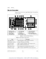
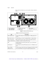
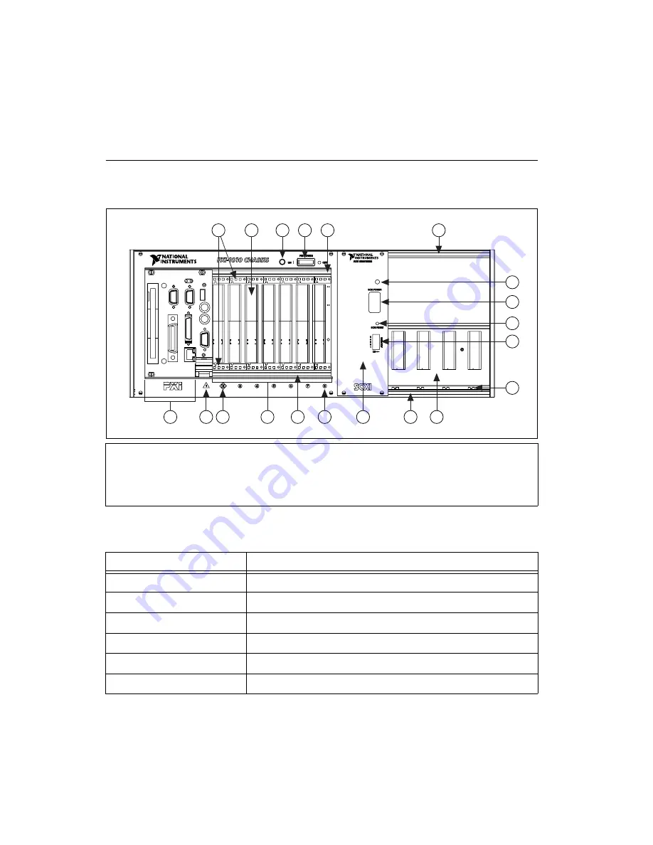
Figure 1-2 shows the front view of the PXI-1010. Table 1-2 describes the
front view items.
Figure 1-2.
Front View of the PXI-1010 Chassis
1
PXI Module Guides
2
PXI Backplane Connectors
3
PXI Indicator Light
4
PXI Power Switch
5
Front Threaded Strips
6
SCXI Indicator Light
7
SCXI Power Switch
8
SCXI Reset Button
9
DIP Switches
10 SCXI Module Guides
11 SCXI Backplane
12 SCXI Slot 0/Power Supply
13 PXI SCXI Control Slot
14 PXI Peripheral Slots
15 PXI Star Trigger Slot
16 PXI System Controller Slot
17 PXI Controller Expansion Slots
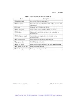
Table 1-2.
PXI-1010 Chassis Front View Items
Item
Description
PXI module guides
Guide PXI modules to mate with PXIbus connectors
PXI backplane connectors
Connects PXI modules to the PXIbus
PXI indicator light
When lit, indicates that the PXI subsystem is powered on
PXI power switch
Turns the PXI subsystem on and off
Front-threaded strips
Secure modules in the chassis and attach front panels
SCXI indicator light
When lit, indicates that the SCXI subsystem is powered on
1
2
4
4
5
5
9
8
7
6
10
17
16 15
14
5
13
12
5
11
Artisan Technology Group - Quality Instrumentation ... Guaranteed | (888) 88-SOURCE | www.artisantg.com


