manualshive.com logo in svg
background image

4

|

ni.com

|

NI CVS-1458 Getting Started Guide

Configuring the Hardware

Remove the NI CVS-1458 from the package and inspect the system for damage. Notify National 

Instruments if the system appears damaged in any way. Do not use a damaged system.

Ensure that the AC input to the external power supply is disconnected before plugging in or 

unplugging any connector. Ground the unit to minimize the possibility of static electricity 

damage.

Complete the following sections to wire power to the NI CVS-1458, connect cameras, and 

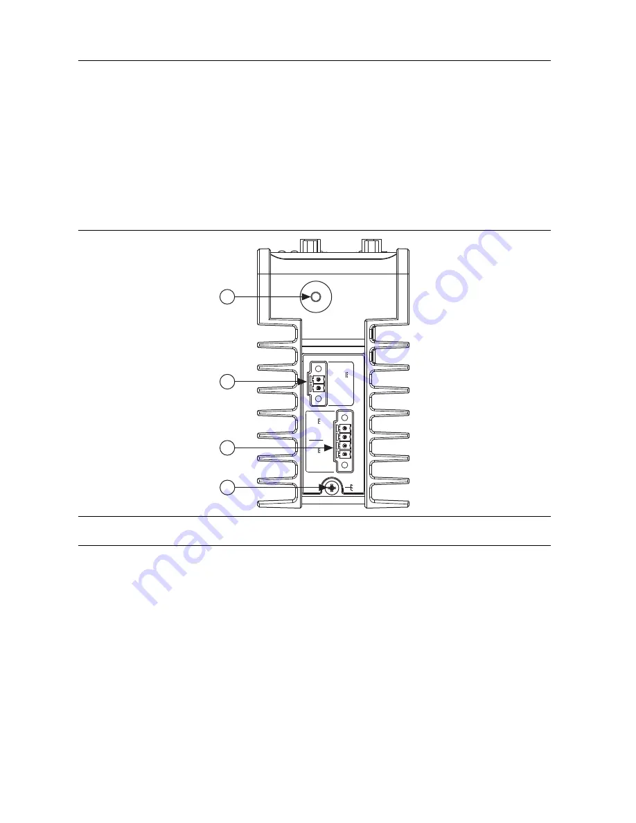
connect the NI CVS-1458 to a network. Figure 1 and Figure 2 show the features on the device.

Figure 1.  

NI CVS-1458 Power Connectors and Reset Button

1

Reset Button

2

System Power Connector

3

Isolated Output and PoE Power Connector

4

Chassis Grounding Screw

S

YSTEM

Po

E

48 V

IS

O

C

ISO

C

Po

E

V

Po

E

V

ISO

5-24

 V

12

-24

 V

C  


V

2

3

1

4

Содержание NI CVS-1458

Страница 1: ...T Ethernet cable per GigE Vision camera One CAT 5 10 100Base TX CAT 5e or CAT 6 1000Base T Ethernet cable to connect the device to a network Note A CAT 5e or CAT 6 1000Base T Ethernet cable is requir...

Страница 2: ...182845 01 for 1 meter cable part number 182845 02 for 2 meter cable or part number 182845 03 for 3 meter cable Safety Information Caution The following paragraphs contain important safety information...

Страница 3: ...You must insulate signal connections for the maximum voltage for which the device is rated Do not exceed the maximum ratings for the device Remove power from signal lines before connection to or disco...

Страница 4: ...gging in or unplugging any connector Ground the unit to minimize the possibility of static electricity damage Complete the following sections to wire power to the NI CVS 1458 connect cameras and conne...

Страница 5: ...the negative and positive leads of the power source approximately 50 to 75 mm 2 to 3 in from the end of the power input wires as shown in Figure 3 Figure 3 Installing a Ferrite on the Power Leads 1 VG...

Страница 6: ...l screw to 0 2 to 0 25 N m 1 8 to 2 2 lb in of torque 6 Install the power connector plug into the SYSTEM power receptacle on the NI CVS 1458 chassis and tighten the connector screws to 0 4 N m 3 5 lb...

Страница 7: ...of the isolated outputs power source to the CISO terminal of the power connector plug and tighten the terminal screw to 0 2 to 0 25 N m 1 8 to 2 2 lb in of torque 6 Connect the positive lead of the Po...

Страница 8: ...illuminate 3 Verify the ACTIVITY LINK LED is lit Acquiring an Image in MAX 1 Open Measurement Automation Explorer MAX 2 In the Configuration Pane expand Devices and Interfaces 3 Select the camera you...

Страница 9: ...O 4 TTL 1 Bidirectional TTL I O 5 GND Digital ground reference for TTL and differential I O 6 TTL 2 Bidirectional TTL I O 7 TTL 3 Bidirectional TTL I O 8 GND Digital ground reference for TTL and diffe...

Страница 10: ...pose isolated input 33 CISO Common ground reference for isolated inputs and outputs 34 Iso In 2 General purpose isolated input 35 Iso In 3 General purpose isolated input 36 CISO Common ground referenc...

Страница 11: ...n You can also access context help within Vision Builder AI by clicking the Show Context Help button on the Vision Builder AI toolbar Examples of Vision Builder AI inspections are installed to the Vis...

Страница 12: ...e is your complete resource for technical support At ni com support you have access to everything from troubleshooting and application development self help resources to email and phone assistance fro...

Отзывы: