


Chapter 3
Signal Connections
NI 951x User Manual
3-6
ni.com
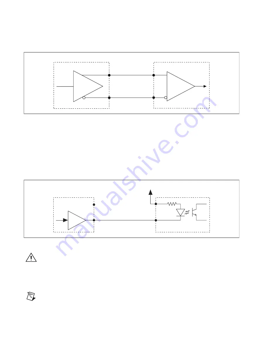
When connecting to drives with differential receiver inputs, configure the
output type in software to differential and connect as shown in Figure 3-2.
Figure 3-2.
Differential Step and Direction Output Connection
Many stepper drive manufacturers offer opto-isolated inputs for
Step (CW)/Direction (CCW) signals. When connecting to opto-isolated
inputs, configure the Step output type to single-ended, connect the NI 9512
Step+ output to the negative (cathode) side of the optocoupler input, and
leave the Step– output on the NI 9512 disconnected. Connect the positive
(anode) side of the drive input to a supply as specified by the drive
manufacturer. Figure 3-3 shows a single-ended connection example.
Figure 3-3.
Opto-Isolated Step and Direction Output Connection
Caution
If the optocoupler input does not include its own current-limiting resistor, you
must provide an external resistor in series with the NI 9512 output. To prevent damage to
the NI 9512 drive interface module or stepper drive, use a resistor that limits the current to
a value below the maximum specifications of the drive interface module and stepper drive.
Refer to Appendix A,
Specifications
, for more information.
Note
Refer to Appendix B,
Position Command Connections
, for position command signal
descriptions and information about connecting the NI 9512 module to drives that support
position command mode.
NI 9512
Step– / Dir– Output
Step+ / Dir+ Output
Receiver
Drive
NI 9512
Step+/Dir+
Drive
Step+/Dir+
Step–/Dir–
+5 V
No Connection
Step–/Dir–