background image

can push this switch to the ON position to unlock a chassis that was previously locked in
MAX.

NO APP Switch

Push the NO APP switch to the ON position to prevent a LabVIEW Real-Time startup
application from running at startup. If you want to permanently disable a LabVIEW Real-Time
application from running at startup, you must disable it in LabVIEW. To run an application at
startup, push the NO APP switch to the OFF position, create an application using the
LabVIEW Application Builder, and configure the application in LabVIEW to launch at
startup. If you already have an application configured to launch at startup and you push the
NO APP switch from ON to OFF, the startup application is automatically enabled. For more
information about automatically launching VIs at startup and disabling VIs from launching at
startup, refer to the 

LabVIEW Help

.

USER1 Switch

You can define the USER1 switch for your application. To define the purpose of this switch in
your embedded application, use the RT Read Switch VI in your LabVIEW Real-Time
embedded VI. For more information about the RT Read Switch VI, refer to the 

LabVIEW

Help

.

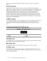
Understanding LED Indications

Figure 7.

  cRIO-9002/9004 LEDs

1

2

3

4

1. POWER
2. BACKUP

3. STATUS
4. USER1

POWER LED

The POWER LED is lit while the cRIO-9002/9004 is powered on. This LED indicates that the
power supply connected to the chassis is adequate.

BACKUP LED

The Backup LED is lit when the controller is drawing power from the V2 terminal.

STATUS LED

The STATUS LED is off during normal operation. The cRIO-9002/9004 indicates specific
error conditions by flashing the STATUS LED a certain number of times every few seconds, as
shown in the following table

10

  | 

ni.com

  | 

NI cRIO-9002/9004 User Manual and Specifications

Содержание CompactRIO cRIO-9002

Страница 1: ...ruments cRIO 9004 Manual Get Pricing Availability at ApexWaves com Call Today 1 800 915 6216 Email sales apexwaves com https www apexwaves com modular systems national instruments compactrio controlle...

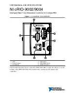
Страница 2: ...9002 9004 2 6 1 3 4 5 INPUT 9 35 V 17 W MAX __ 1 LEDs 2 Power Connector 3 DIP Switches 4 Reset Button 5 RJ 45 Ethernet Port 6 RS 232 Serial Port This document describes how to connect the cRIO 9002 9...

Страница 3: ...he area is known to be nonhazardous Caution Substitution of components may impair suitability for Class I Division 2 Caution For Division 2 and Zone 2 applications install the system in an enclosure r...

Страница 4: ...he product documentation Furthermore any changes or modifications to the product not expressly approved by National Instruments could void your authority to operate it under your local regulatory rule...

Страница 5: ...mm 3 47 in 44 2 mm 1 74 in 1 1 M4 Thread Complete the following steps to install the controller on the chassis 1 Make sure that no power is connected to the controller or the chassis 2 Align the cont...

Страница 6: ...better shielded twisted pair Ethernet cable to connect the chassis to an Ethernet hub or use an Ethernet crossover cable to connect the chassis directly to a computer Caution To prevent data loss and...

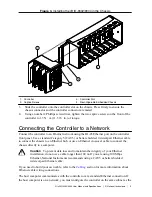
Страница 7: ...o the Controller Caution You must install the controller on a CompactRIO chassis and tighten the captive screws before you apply power to the controller Installing the controller while power is applie...

Страница 8: ...mmon ground Powering On the cRIO 9002 9004 Plug in each power supply to the CompactRIO system The controller runs a power on self test POST During the POST the Power Status and User1 LEDs turn on The...

Страница 9: ...r either with or without cycling power Connecting Serial Devices to the cRIO 9002 9004 The cRIO 9002 9004 has an RS 232 serial port to which you can connect devices such as displays or input devices U...

Страница 10: ...th no software installed on the drive Refer to the Measurement Automation Explorer Help for more information about installing software on a controller and reformatting the drive on the controller CONS...

Страница 11: ...startup and disabling VIs from launching at startup refer to the LabVIEW Help USER1 Switch You can define the USER1 switch for your application To define the purpose of this switch in your embedded a...

Страница 12: ...he controller has detected an unrecoverable error Contact National Instruments Solid The flash memory card on the controller is corrupt Reformat the hard drive on the controller Refer to Measurement A...

Страница 13: ...ent Product misuse can result in a hazard You can compromise the safety protection built into the product if the product is damaged in any way If the product is damaged return it to NI for repair Netw...

Страница 14: ...9 V or higher but when these devices are powered on they can run on as little as 6 V Physical Characteristics If you need to clean the module wipe it with a dry towel Tip For two dimensional drawings...

Страница 15: ...nt circuits powered by regulated low voltage sources and electronics Note Measurement Categories CAT I and CAT O are equivalent These test and measurement circuits are not intended for direct connecti...

Страница 16: ...4 35 EU Low Voltage Directive safety 2014 30 EU Electromagnetic Compatibility Directive EMC 94 9 EC Potentially Explosive Atmospheres ATEX Online Product Certification Refer to the product Declaration...

Страница 17: ...mers For additional environmental information refer to the Minimize Our Environmental Impact web page at ni com environment This page contains the environmental regulations and directives with which N...

Страница 18: ...orldwide Support and Services The NI website is your complete resource for technical support At ni com support you have access to everything from troubleshooting and application development self help...

Страница 19: ...rademarks and Logo Guidelines at ni com trademarks for information on NI trademarks Other product and company names mentioned herein are trademarks or trade names of their respective companies For pat...

Отзывы: