


Chapter 9:
Modeling Example
VSP User Manual
77
Version 1.7.92
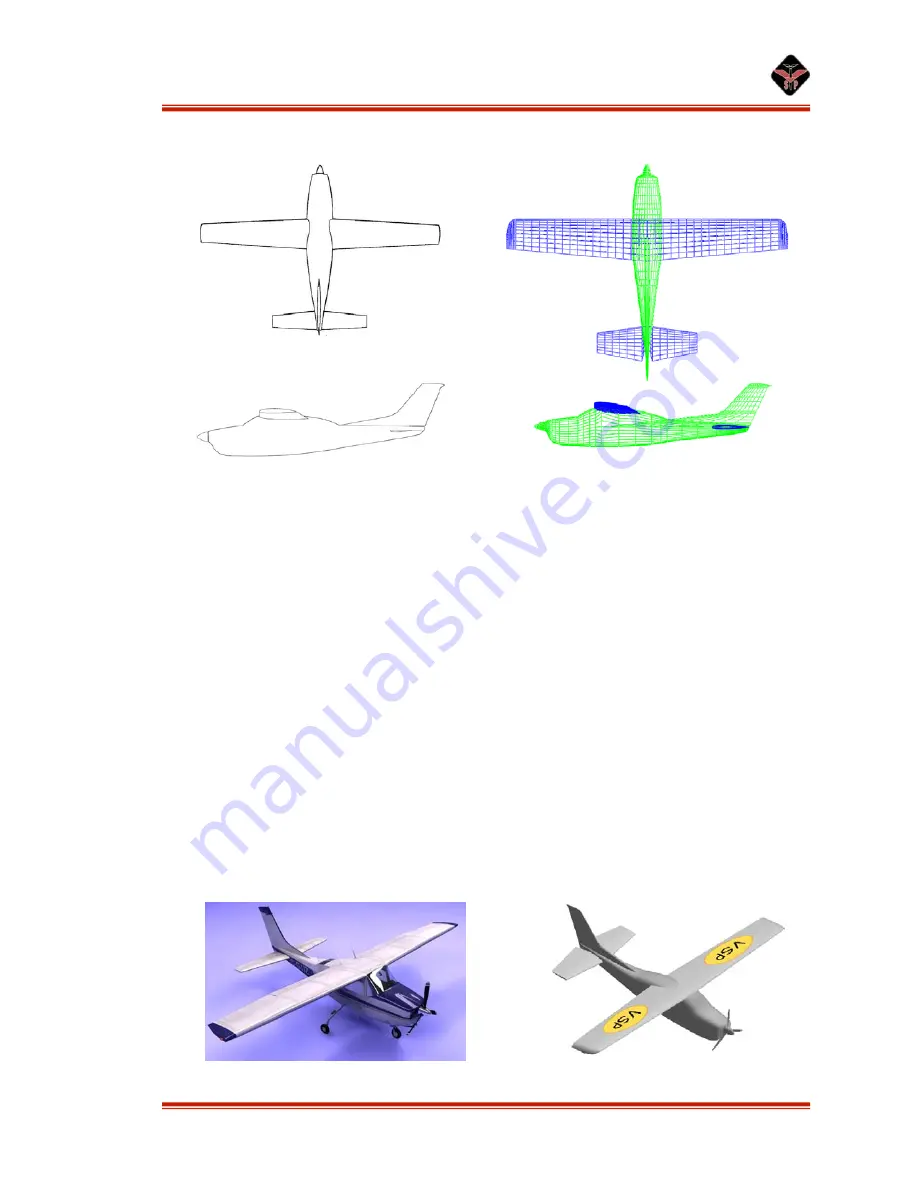
At this point, the aircraft should look roughly as follows:
Figure 72: Top and profile views of Cessna 210.
Prop
This is one of the easier steps. Just locate the prop correctly, and change the
stations on the prop to suit.
For the spinner, there are 2 schools of thought. First is to make the spinner and
the rest of the fuselage one part. The other school of thought is to have the spinner,
canopy, and all the other pieces as separate parts. The advantage to the first method is
that the transition between the pieces is smooth because it is all the same part in VSP.
The advantage to the second is that all of the taper ratios can be used more than once.
The fuselage, spinner, and canopy might require different taper ratios, but with the first
method all of the required extra cross sections must be added in manually. Which
method is employed is considered purely a matter of personal preference.
Once the model is laid out, add texture and shading to suit. VSP does not feature
photo-realistic surface rendering, however some basic shading and texturing is possible.
When finished, the final model should appear as follows:
Figure 73: Three-view of Cessna 210 and VSP model.


