


Chapter 5:
Designing the Fuselage
VSP User Manual
28
Version 1.7.92
Explanation:
To use IML, first turn the IML on. The on/off buttons are just beneath the
IML title bar in the Shape tab. Select a color that will easily differentiate the inner mold
line from the fuselage. Then for each fuselage cross section, set the target wall thickness;
the actual wall thickness will be shown to the right.
Note
: There are cases when these wall thickness values don’t agree. The
IML function attempts to keep the aspect ratio of the cross section
constant, so the wall thickness might not always be constant.
The
Modify
variable beneath the Wall Thickness sliders allows the user to modify
either the Inner Mold Line (IML) or Outer Mold Line (OML). When using an inner mold
line, the Modify buttons allow one to set the wall thickness for each mold line
parametrically. Note that changing wall thicknesses of any fuselage section when the
IML button is selected will change the shape of the
exterior
of the fuselage, and changing
wall thicknesses when the OML button is selected will change the shape of the
inner
shape of the fuselage.
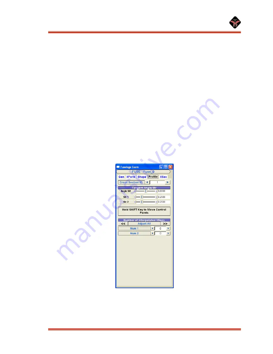
Profile Tab
Figure 17: Fuselage Profile tab.
Cross Section ID:
Use the arrows to access each cross section for editing purposes.


