Location and clearances
If the stove is to be installed on a combustible floor, it must be installed on sheet metal or a tile. The oil drip tray, 72636 (not
supplied) is a suitable substitute for either of these two pads.
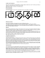
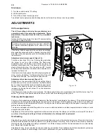
Maintain these minimum clearances to combustibles (fig. 2) :
A
12 inches (300 mm)
B
19 inches (483 mm)
C
12 inches (300 mm)
If reduced clearances are needed, obtain requirements from your local building code authorities.
Safety precautions
Please read the installation instructions carefully, prior to installing the oil stove.
Your Napoleon oil stove must be installed in accordance with all national and local building code standards.
Consult the authority having jurisdiction (such as municipal building department, fire department, fire prevention bureau,
etc.) to determine the need to obtain a permit. If you are in doubt about the proper installation for your situation, contact
your dealer or local building or fire official.
Draft air
Most of the heat generated by the oil stove is used to warm the room air. However, part of the generated heat escapes as
exhaust gas through the chimney, creating a ‘chimney draft’. To ensure proper operations of the stove, it must be
connected to a chimney having a sufficient draft capacity to operate the stove satisfactorily.
Flue draft, measured as negative pressure in the chimney, is created by the hot, rising combustion gas. The draft, in turn,
permits combustion air to enter the burner and emit the exhaust gases from the chimney to complete the combustion cycle.
For the 10 kW, a draft of 0.072" (or 18 Pa) water column for maximum input burn and 0.032" (or 8 Pa) for minimum input
burn is rated best to obtain the utmost performance of the oil stove.
Basic criteria essential to create and maintain chimney draft are :
1.
Availability of combustion air.
2.
Diameter and height of chimney.
3.
Heat generated by the fire.
These segments work together to create the chimney draft. To alter one of them will affect the other two and change the
amount of draft in the chimney and ultimately the stove’s performance. To ensure that adequate chimney draft is
maintained, the chimney should be kept clean and without cracks. As soon as the oil stove has been installed, the chimney
draft should be checked with a draftmeter. Remove the screw located on the flue collar to introduce the draftmeter, replace
the screw once all the necessary tests will have been carried out. Flue draft is measured when the oil stove is hot (after a
minimum use of 30 minutes) to establish a true reading of the draft.
For the recommended operating draft level, see ‘General Information’ on page 4. Draft adjustment can be made through
use of the draft regulator located at the back of the oil stove (2, figure 11, page 8). In the event that the chimney draft is
excessive or irregular, a draft stabiliser should to be fitted to chimney connector.
Combustion air
The oil burning stove consumes about 4000 ft3 of air per US gallon of oil (30 m3 of air per litre of oil). This air is introduced
into the burner through air inlets and exits the chimney as combustion gas. For the oil stove to function properly, an
adequate supply of combustion air is required. There are many other appliances in your home competing for air such as :
a kitchen range hood, forced air heating devices, clothes dryer or a bathroom exhaust fan. Clothes dryers exhaust 400
CFM (cubic feet / minute) ; range hoods and exhaust fans can exhaust up to 150 CFM. If there is insufficient combustion air,
you may need to open a door or window to avoid adversely affecting the performance of the oil stove.
The manufacturer of the stove and/or his agent is not responsible for any smoking or related problems or damages
resulting from the lack of adequate combustion air. It is the responsibility of the installation contractor to ensure that
adequate combustion air is available to the stove at all times.
Document n° 1092-1 EN ~ 04/02/2002
5
A
B
C
C
C
C
B
A
Figure 2
Содержание OS10-3
Страница 15: ...Document n 1092 1 EN 04 02 2002 15 Notes...


