background image

63.7A

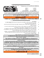
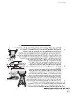
ÉVENT DE TYPE « A

 » 

CHEMINÉE POUR 

COMBUSTION AU 

BOIS ET RACCORD 

D’ÉVACUA

TION

(GAINE NÉCES-

SAIRE SI LE 

DIAMÈTRE

INTÉRIEUR EST 

DE 6” OU PLUS)

PAROI 

SIMPLE OU 

ÉVENT DE 

TYPE « B »

CHEMINÉE EN MAÇON-

NERIE + RACCORD 

D’ÉVACUA

TION 

(AUCUNE GAINE 

NÉCESSAIRE SI 

LE DIAMÈTRE EST 

DE 4-5”)

PAROI 

SIMPLE OU 

ÉVENT DE 

TYPE « B »

ÉVENT DE TYPE 

« B » SYSTÈME 

D'ÉVACUA

TION 

POUR APPAREIL


AU GAZ

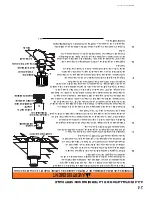
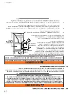
UNE CHEMINÉE SERV

ANT D’ÉVACUA

TION À CET APP

AREIL NE DOIT P

AS SERVIR POUR UN 

APPAREIL

 DE CHAUFFAGE À COMBUSTIBLE SOLIDE.

!

AVERTISSEMENT

Une cheminée servant d’évacuation à cet appareil ne doit pas servir pour un appareil de chauffage à 

combustible solide.

T outes les courses horizontales doivent avoir une élévation minimale de 1/4” par pied.

Trois types de systèmes de cheminée peuvent être utilisés avec cet appareil.

27

W415-0153 / C / 10.11.1

1

4.7 

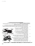
SPÉCIFICATION POUR LE TIRA

GE NA

TUREL

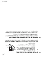
4.7.1 INSTALLA

TION DE LA CHEMINÉE

Содержание Haliburton GDS28N

Страница 1: ...ny phone in your building Immediately call your gas supplier from a neighbour s phone Follow the gas supplier s instructions If you cannot reach your gas supplier call the fire department Installation and service must be performed by a qualified installer service agency or the supplier This appliance may be installed in an aftermarket permanently located manufactured home USA only or mobile home w...

Страница 2: ...ROTECTION 21 4 2 1 HORIZONTAL INSTALLATION 21 4 2 2 VERTICAL INSTALLATION 22 4 2 3 HORIZONTAL AIR TERMINAL INSTALLATION MODEL GDS28 22 4 2 4 VERTICAL AIR TERMINAL INSTALLATION 23 4 3 APPLIANCE VENT CONNECTION 24 4 4 MOBILE HOME INSTALLATION MODEL GDS28 24 4 5 GAS INSTALLATION 25 4 6 OPTIONAL WALL SWITCH THERMOSTAT REMOTE 25 4 7 NATURAL VENT SPECIFICS 26 4 7 1 CHIMNEY INSTALLATION 26 4 7 2 INSTALLI...

Страница 3: ...3 W415 0153 E 05 28 12 Door see DOOR CLOSING OPENING section Rating plate see RATING PLATE section Logo see LOGO PLACEMENT section Vent see VENTING section 1 0 INSTALLATION OVERVIEW ...

Страница 4: ...ntrol compartments burners and circulating blower and its passageway in the appliance and venting system are kept clean The appliance and its venting system should be inspected before use and at least annually by a qualified service person More frequent cleaning may be required due to excessive lint from carpeting bedding material etc The appliance area must be kept clear and free from combustible...

Страница 5: ...installation in a bedroom or bathroom unless the unit is a direct vent sealed combustion product ALWAYS LIGHT THE PILOT WHETHER FOR THE FIRST TIME OR IF THE GAS SUPPLY HAS RUN OUT WITH THE GLASS DOOR OPENED OR REMOVED PROVIDE ADEQUATE CLEARANCE FOR SERVICING AND OPERATING THE APPLIANCE PROVIDE ADEQUATE VENTILATION NEVER OBSTRUCT THE FRONT OPENING OF THE APPLIANCE OBJECTS PLACED IN FRONT OF THE APP...

Страница 6: ...ow in the room where the appliance is to be located should be considered If possible you should choose a location where the vent will pass through the house without cutting a floor or roof joist If the appliance is installed directly on carpeting vinyl tile or other combustible material other than wood flooring the appliance shall be installed on a metal or wood panel extending the full width and ...

Страница 7: ...bsence of specific recommendations from the local authority having jurisdiction the certified high altitude input rating shall be reduced at the rate of 4 for each ad ditional 1 000 ft Change in flame appearance from HI to LO is more evident in natural gas than in propane Expansion contraction noises during heating up and cooling down cycles are normal and to be expected This appliance may be inst...

Страница 8: ...S COMMUNAUTES ANSI NFPA 501A STEADY STATE EFFICIENCY NG 75 FAN OFF 78 FAN ON STEADY STATE EFFICIENCY LP 75 FAN OFF 79 FAN ON EFFICACITE CONSTANTE GN 75 VENT ARRETE 78 VENT FONCTIONNE EFFICACITE CONSTANTE GP 75 VENTILATEUR ARRETE 79 VENTILATEUR FONCTIONNE STEADY STATE EFFICIENCYAPPLIES TO CANADA ONLY L EFFICACITE CONSTANTE S APPLIQUENT SEULEMENTAU CANADA AFUE NG LP GN GP 64 65 MINIMUM AND MAXIMUM H...

Страница 9: ... SYSTEM MUST BE SUPPORTED EVERY 3 FEET FOR BOTH VERTICAL AND HORIZONTAL RUNS USE SUPPORTS OR EQUIVALENT NON COMBUSTIBLE STRAPPING TO MAINTAIN THE REQUIRED CLEARANCE FROM COMBUSTIBLES USE WOLF STEEL LTD SUPPORT RING ASSEMBLY W010 0370 OR EQUIVALENT NON COMBUSTIBLE STRAPPING TO MAINTAIN THE MINIMUM CLEARANCE TO COMBUSTIBLES FOR BOTH VERTICAL AND HORIZONTAL RUNS SPACERS ARE ATTACHED TO THE INNER PIPE...

Страница 10: ...erminal kit GD175 7 12 of venting included or 1 12 to 7 12 pitch roof terminal kit GD110 8 12 to 12 12 roof terminal kit GD111 flat roof terminal kit GD112 or periscope kit GD180 for wall penetration below grade in conjunction with the appropriate venting components For optimum flame appearance and appliance operation keep the vent length and number of elbows to a minimum It is recommended that al...

Страница 11: ...11 W415 0153 E 05 28 12 3 2 TYPICAL VENT INSTALLATION 26 3 4 16 MINIMUM 40 FEET MAXIMUM 3 MINIMUM 26 3 4 29 MINIMUM 55 3 4 MINIMUM PLUS RISE 34 MAXIMUM See VENTING section ...

Страница 12: ...eriscope must be installed so that when final grading is completed the bottom air slot is located a minimum 12 above grade The maximum allowable vent length is 10 for a fireplace and 8 for a stove 9 1A 3 3 SPECIAL VENT INSTALLATIONS 29 MINIMUM 12 MIN TO GRADE 26 3 4 3 3 1 PERISCOPE TERMINATION ...

Страница 13: ...adjacent wall including neighbouring buildings P 8 8 Roof must be non combustible without openings Q 3 3 See chart for wider wall dimensions R 6 6 See chart for deeper wall dimensions The terminal shall not be installed on any wall that has an open ing between the terminal and the open side of the structure S 12 12 Clearance under a covered balcony Δ The terminal shall not be located less than 6 f...

Страница 14: ...ual to or greater than the horizontal run Vertical rise is less than horizontal run Vertical rise is equal to or greater than the horizontal run Vertical rise is less than horizontal run Horizontal run vertical rise to maximum of 40 feet Horizontal run vertical rise to maximum of 24 75 feet Horizontal run vertical rise to maximum of 40 feet Horizontal run vertical rise to maximum of 40 feet 4 2 ti...

Страница 15: ...5 2 4 5 FT HO 03 three 90 elbows 90 03 270 90 5 4 FT HT HR HO 4 5 5 4 9 9 FT HT VT 9 9 11 20 9 FT Formula 1 HT VT 9 9 11 Formula 2 HT VT 40 FT 20 9 40 Since both formulas are met this vent configuration is acceptable See graph to determine the required vertical rise VT for the required horizontal run HT The shaded area within the lines represents acceptable values for HT and VT 0 2 5 5 7 5 10 12 5...

Страница 16: ...mple V1 VT 6 FT H1 3 FT H2 5 FT HR H1 H2 3 5 8 FT HO 03 two 90 elbows 90 03 180 90 2 7 FT HT HR HO 8 2 7 10 7 FT HT VT 10 7 6 16 7 FT Formula 1 HT 4 2 VT 4 2 VT 4 2 x 6 25 2 FT Formula 2 HT VT 24 75 FT 16 7 24 75 Since both formulas are met this vent configuration is acceptable 90 V1 H1 H2 90 Example V1 4 FT V2 1 5 FT VT V1 V2 4 1 5 5 5 FT H1 2 FT H2 1 FT H3 1 FT H4 1 5 FT HR H1 H2 H3 H4 2 1 1 1 5...

Страница 17: ...ws the following formulas apply Formula 1 HT VT Formula 2 HT VT 40 feet Example V1 5 FT V2 6 FT V3 10 FT VT V1 V2 V3 5 6 10 21 FT H1 8 FT H2 2 5 FT HR H1 H2 8 2 5 10 5 FT HO 03 four 90 elbows 90 03 360 90 8 1 FT HT HR HO 10 5 8 1 18 6 FT HT VT 18 6 21 39 6 FT Formula 1 HT VT 18 6 21 Formula 2 HT VT 40 FT 39 6 40 Since both formulas are met this vent configuration is acceptable 90 V1 V2 H1 H2 The s...

Страница 18: ...3 2 1 1 5 4 5 FT H1 6 FT H2 2 FT HR H1 H2 6 2 8 FT HO 03 four 90 elbows 90 03 360 90 8 1 FT HT HR HO 8 8 1 16 1 FT HT VT 16 1 4 5 20 6 FT Formula 1 HT 3VT 3VT 3 x 4 5 13 5 FT 16 1 13 5 Since this formula is not met this vent configuration is unacceptable Formula 2 HT VT 40 feet 20 6 40 Since only formula 2 is met this vent configuration is unacceptable and a new appliance location or vent configur...

Страница 19: ...nce NOTE A vent adaptor will be required directly off the appliance Follow vent manufacturer s installation instructions Different manufacturer s venting components must not be combined Once the preferred manufacturer s appliance adaptor has been attached the remainder of the system must be that of the same manufacturer The only exception to this rule is to use Wolf Steel s approved 3 flex liner a...

Страница 20: ...IATION IMPROPER SUPPORT OF THE ENTIRE VENTING SYSTEM MAY ALLOW VENT TO SAG AND SEPARATE USE VENT RUN SUPPORTS AND CONNECT VENT SECTIONS PER INSTALLATION INSTRUCTIONS RISK OF FIRE DO NOT ALLOW LOOSE MATERIALS OR INSULATION TO TOUCH THE VENT PIPE REMOVE INSULATION TO ALLOW FOR THE INSTALLATION OF THE ATTIC SHIELD AND TO MAINTAIN CLEARANCES TO COMBUSTIBLES 68 2A 4 1 MINIMUM CLEARANCES TO COMBUSTIBLES...

Страница 21: ...e firestop assembly Dry fit the firestop assembly before proceeding to ensure the brackets on the rear surface fit to the inside surface of the horizontal framing The length of the vent shield may be cut shorter for combustible walls that are less than 8 1 2 thick but the vent shield must extend the full depth of the combustible wall A Assemble the shield to the spacer as shown using the 3 shorter...

Страница 22: ...insulation from filling up the 1 air space around the pipe 21 1 CAULKING VENT PIPE SHIELD FIRESTOP UNDERSIDE OF JOIST VENT PIPE COLLAR VENT PIPE SHIELD A Stretch the inner flex pipe to the required length taking into account the additional length needed for the finished wall surface Apply a heavy bead of the high temperature sealant W573 0007 Mill Pac not supplied to the inner sleeve of the air te...

Страница 23: ...ctor leaving a min 3 4 of the air terminal connector showing above the top of the flashing Slide the flashing underneath the sides and upper edge of the shingles Ensure that the air terminal connector is properly centred within the flashing giving a 3 4 margin all around Fasten to the roof Do not nail through the lower portion of the flashing Make weather tight by sealing with caulking Where possi...

Страница 24: ...llation is completed An optional decorative black band is available for this use In the event that the venting must be disassembled care must be taken to reseal the venting 28 3 2 OVERLAP HIGH TEMPERATURE SEALANT 8 X 1 2 SELF DRILLING SCREWS 4 3 APPLIANCE VENT CONNECTION 4 4 MOBILE HOME INSTALLATION MODEL GDS28 In Canada mobile home installation may be vented horizontally or vertically In the Unit...

Страница 25: ...N ATTACHING GAS SUPPLY PIPE TO PREVENT DAMAGING GAS LINE ALWAYS LIGHT THE PILOT WHETHER FOR THE FIRST TIME OR IF THE GAS SUPPLY HAS RUN OUT WITH THE GLASS DOOR OPENED OR REMOVED PURGING OF THE GAS SUPPLY LINE SHOULD BE PERFORMED BY A QUALIFIED SERVICE TECHNICIAN ASSURE THAT A CONTINUOUS GAS FLOW IS AT THE BURNER BEFORE CLOSING THE DOOR ENSURE ADEQUATE VENTILATION FOR GAS AND ELECTRICAL LOCATIONS S...

Страница 26: ...LINED CHIMNEY VENT CONNECTOR NO NEW LINER NEEDED IF OLD LINER DIAMETER IS 4 5 SINGLE WALL OR B VENT B VENT LIQUID FUEL GAS BURNING CHIMNEY A CHIMNEY VENTING THIS APPLIANCE SHALL NOT VENT ANY SOLID FUEL BURNING APPLIANCE WARNING A chimney venting this appliance shall not vent any solid fuel burning appliance All horizontal runs must have a 1 4 rise per foot Three types of chimney systems may be use...

Страница 27: ...crew the wire access cover plate from the rear right hand side below the firebox Remove and discard the gasket Re move the knockout from the cover plate and insert the protec tive bushing Pull both spill switch wires through the bushing taking up any slack Replace the cover plate Connect one wire end to the terminal block and the other end to terminal 1 of the gas valve Connect the two wires runni...

Страница 28: ...gher than any wall roof building or obstacle within 10 feet horizontally 59 1A 3 FT MIN 3 FT MIN 3 FT MIN 3 FT MIN 10 FT OR MORE LESS THAN 10 FT FLAT ROOF WALL 2 FT MIN 10 FT TO NEAREST ROOFLINE RIDGE LESS THAN 10 FEET 2 FT MIN 2 FT MIN 4 7 4 COMBUSTION AIR This appliance needs air for safe operation and must be installed in such a way that adequate combustion air is available 4 7 5 ADDING VENT SE...

Страница 29: ...LIANCE OFF AND WAIT UNTIL APPLIANCE IS COOL TO THE TOUCH DOORS ARE HEAVY AND FRAGILE SO HANDLE WITH CARE 75 3 When installing the fire viewing door a simple procedure must be followed in order to not damage the door A Open both side doors exposing the bushings on the left and the latches on the right B Align the pins on the door to the bushings Lower into place until both bushings touch C Engage t...

Страница 30: ... installation Use only certified PHAZERTM logs glowing embers and charcoal embers available from your local authorized dealer distributor Log colours may vary During the initial use of the appliance the colours will become more uniform as colour pigments burn in during the heat activated curing process 5 2 LOG PLACEMENT WARNING FAILURE TO POSITION THE LOGS IN ACCORDANCE WITH THESE DIAGRAMS OR FAIL...

Страница 31: ...d in the bottom of the bag should not be used NOTE Charcoal embers are not to be placed on the burner 31 1 Tear the glowing embers into pieces and place onto the screen beneath the front log Care should be taken to shred the embers into thin small irregular pieces as only the exposed edges of the fibre hairs will glow when exposed to direct flame WARNING DO NOT BLOCK THE BURNER PORTS BLOCKED PORTS...

Страница 32: ...t fans in the home turn appliance blower off if equipped B Set controls to high and light the appliance C Wait 5 minutes Light a match and extend it 1 into the hole located above the spill switch bracket on the adaptor D Venting action is satisfactory if the flame stays lit Venting action is unsatisfactory if the flame extinguishes E If venting action is unsatisfactory turn the appliance off wait ...

Страница 33: ...gas control which has been under water WHAT TO DO IF YOU SMELL GAS Turn off all gas to the appliance Open windows Do not try to light any appliance Do not touch any electric switch do not use any phone in your building Immediately call your gas supplier from a neighbour s phone Follow the gas supplier s instructions If you cannot reach your gas supplier call the fire department LIGHTING INSTRUCTIO...

Страница 34: ...Check that main burner is operating on HI AFTER TAKING PRESSURE READINGS TIGHTEN SCREWS FIRMLY TO SEAL DO NOT OVER TORQUE LEAK TEST 39 3 P I P I L O T N O L O T HI L O F F O A B PILOT SCREW PILOT BURNER THERMOCOUPLE THERMOPILE 7 2 VENTURI ADJUSTMENT This appliance has an air shutter that has been factory set open according to the chart below Regardless of venturi orientation closing the air shutte...

Страница 35: ...1 2 OF THERMOCOUPLE THERMOPILE 7 4 RESTRICTING VERTICAL VENTS 77 3 Vertical installations may display a very active flame If this appearance is not desirable the vent exit must be restricted using a restrictor vent kit Refer to ACCESORIES in the REPLACEMENTS section for the ap propriate kit This will reduce the velocity of the exhaust gases slowing down the flame pattern and creating a more tradit...

Страница 36: ...ing which can be distributed in the surrounding living area F Check to see that the main burner ignites completely on all openings when turned on A 5 to 10 second total light up period is satisfactory If ignition takes longer consult your local authorized dealer distributor G Check that the gasketing on the sides top and bottom of the door is not broken or missing Replace if necessary H If for any...

Страница 37: ...ither pinched nor interfere with the blower operation Re secure the air intake manifolds INSTALLATION THROUGH THE FIREBOX REPLACEMENT BLOWER ACCESS GASKET IS REQUIRED Turn off the electrical power and the gas supply to the appliance Open the lower control door the two side doors and the fire viewing door Remove the logs Remove the blower access plate held on with 8 screws Disconnect the two blower...

Страница 38: ...IS IS A FAST ACTING THERMOCOUPLE IT IS AN INTEGRAL SAFETY COMPONENT REPLACE ONLY WITH A FAST ACTING THERMOCOUPLE SUPPLIED BY WOLF STEEL LTD WARNING COMMON COMPONENTS REF NO PART NO DESCRIPTION 1 W725 0042 SIT VALVE NG 1 W725 0043 SIT VALVE LP 2 W100 0056 BURNER 3 W456 0037 37 BURNER ORIFICE NG 3 W456 0054 54 BURNER ORIFICE LP 4 W010 0550 PILOT ASSEMBLY LP 4 W010 0633 PILOT ASSEMBLY NG 5 W455 0052 ...

Страница 39: ...METER 43 BM3730 BLACK TRIM COLLAR 44 W010 0300 10 ALUMINUM FLEX LINER C W SPACERS 4 DIAMETER 45 W025 0003 DECORATIVE BLACK BAND GD180 PERISCOPE TERMINAL KIT 36 BM6790 90 ELBOW 7 DIAMETER 38 BM67ADJ 30 TO 53 ADJUSTABLE PIPE 7 DIAMETER 39 W010 1313 FIRESTOP WALL PLATE 40 W585 0267 TOP VENT SHIELD 41 W020 0032 HARDWARE 42 BM6724 24 STOVE PIPE 7 DIAMETER 43 BM3730 BLACK TRIM COLLAR 44 W010 0300 10 ALU...

Страница 40: ...LD TRIVET 30 GS200 SS SATING CHROME TRIVET 54 W573 0007 HIGH TEMPERATURE SEALANT 55 W660 0081 THERMOSTAT SWITCH 56 F40 ON OFF REMOTE 57 F50 THERMOSTATIC REMOTE 58 GS328 1K DOOR BLACK 58 GS328 1G DOOR GOLD 58 GS328 1SS DOOR SATIN CHROME 59 W175 0124 CONVERSION KIT NG LP 59 W175 0125 CONVERSION KIT LP NG 60 W715 0195 PEDESTAL TRIM GDS28 REF NO PART NO DESCRIPTION 46 GD 201 PERISCOPE 61 BM6745 45 ELB...

Страница 41: ...41 W415 0153 E 05 28 12 28 P I P I L O T N O L O T HI L O F F O 4 5 6 7 1 3 27 29 30 12 14 16 13 15 25 22 23 10 8 34 35 36 37 38 39 40 43 42 45 45 45 45 64 47 48 49 50 51 52 53 46 58 32 31 62 ...

Страница 42: ... valve Faulty valve Replace Pilot burning no gas to main burner gas knob is on HI wall switch thermostat is on Thermostat or switch is defective Connect a jumper wire across the wall switch terminals if main burner lights replace switch thermostat Wall switch wiring is defective Disconnect the switch wires connect a jumper wire across terminals 1 3 if the main burner lights check the wires for def...

Страница 43: ... on HI Outlet pressure can be checked the same as above using screw B Gauge should read 3 5 water column for natural gas or 10 water column for propane Check that main burner is operating on HI AFTER TAKING PRESSURE READINGS BE SURE TO TURN SCREWS CLOCKWISE FIRMLY TO RESEAL DO NOT OVER TORQUE Leak test with a soap and water solution Flames are very aggressive Door is ajar Ensure the mechanical mea...

Страница 44: ...s and see if pilot flame flutters diminishes or extinguishes especially when main burner ignites Monitor appliance supply working pressure Check if supply piping size is to code Correct all undersized piping Remote wall switch is in OFF position main burner comes on when gas knob is turned to ON position Wall switch is mounted upside down Reverse Remote wall switch is grounding Replace Remote wall...

Страница 45: ...er plated trim or other components due to water weather damage long periods of dampness condensation damaging chemicals or cleaners will not be the responsibility of NAPOLEON All parts replaced under the President s Limited Lifetime Warranty Policy are subject to a single claim During the first 10 years NAPOLEON will replace or repair the defective parts covered by the lifetime warranty at our dis...

Страница 46: ...46 W415 0153 E 05 28 12 12 0 SERVICE HISTORY 43 1 ...

Страница 47: ...47 W415 0153 E 05 28 12 ...

Страница 48: ...48 W415 0153 E 05 28 12 ...

Страница 49: ...44 1 48 W415 0153 C 10 11 11 13 0 NOTES ...

Страница 50: ...oblèmes particuliers Travail effectué Nom du technicien Détaillant Historique d entretien Wolf Steel Cet appareil doit être entretenu annuellement selon son usage 47 W415 0153 C 10 11 11 12 0 HISTORIQUE D ENTRETIEN ...

Страница 51: ...dommages causés par les intempéries de longues périodes d humidité la condensation des produits chimiques ou produits d entretien nuisibles ne seront pas la responsabilité de NAPOLÉON Toutes les pièces remplacées en vertu de la politique de Garantie à vie limitée du Président ne peuvent faire l objet que d une seule réclamation Durant les dix premières années NAPOLÉON remplacera ou réparera les pi...

Страница 52: ...son et devrait être enlevée lorsque nécessaire Installation incorrecte Assurez vous que la con guration d évacuation respecte les paramètres d évacuation prescrits GDS28 SYMPTÔME PROBLÈME SOLUTIONS La porte se coince La poussiére saleté adhère aux charnières elle est chauffée et brûle coinçant ainsi la porte Enlevez la porte des charnières en la soulevant Lubri ez les charnières avec du graphite R...

Страница 53: ...tiennent la porte en place Du carbone se dépose sur la vitre les bûches ou les parois de la chambre de combustion Le volet d air est bloqué Assurez vous que l ouverture du volet d air n est pas bloquée par des bres ou autres obstructions La amme ef eure les bûches ou les parois de la chambre de combustion Véri ez si les bûches sont positionnées correctement Augmentez l ouverture du volet d air pou...

Страница 54: ...est à HI l interrupteur mural thermostat est à ON Le thermostat ou l interrupteur sont défectueux Reliez un l de dérivation entre les bornes de l interrupteur mural si le brûleur principal s allume remplacez l interrupteur thermostat Le raccordement de l interrupteur est défectueux Débranchez les ls de l interrupteur et reliez un l de dérivation entre les bornes 1 et 3 si le brûleur principal s al...

Страница 55: ...42 W415 0153 C 10 11 11 28 P I PIL O T N O L O T H I LO F F O 4 5 6 7 1 3 27 29 30 12 14 16 13 15 25 22 23 10 8 34 35 36 37 38 39 40 43 42 45 45 45 45 64 47 48 49 50 51 52 53 46 58 32 31 62 ...

Страница 56: ... SATINÉ 54 W573 0007 SCELLANT À HAUTE TEMPÉRATURE 55 W660 0081 THERMOSTAT 56 F40 TÉLÉCOMMANDE MARCHE ARRÊT 57 F50 TÉLÉCOMMANDE À CONTRÔLE THERMOSTATIQUE 58 GS328 1K ENSEMBLE DE PORTE NOIRE 58 GS328 1G ENSEMBLE DE PORTE OR 58 GS328 1SS PORTE CHROME SATINÉ 59 W175 0124 ENSEMBLE DE CONVERSION GN À PL 59 W175 0125 ENSEMBLE DE CONVERSION PL À GN 60 W715 0195 MOULURE DE PIÉDESTAL GDS28 Nº RÉF Nº DE PIÈC...

Страница 57: ...ÊLE 24 7 DE DIAMÈTRE 43 BM3730 COLLET DE FINITION NOIR 44 W010 0300 GAINE FLEXIBLE DE 10 EN ALUMINIUM AVEC ESPACEURS 4 DIA 45 W025 0003 BANDE DÉCORATIVE NOIRE GD 180 ENSEMBLE PÉRISCOPIQUE 36 BM6790 COUDE DE 90 7 DE DIAMÈTRE 46 GD 201 ENSEMBLE PÉRISCOPIQUE 38 BM67ADJ CONDUIT AJUSTABLE 30 À 53 7 DIA 39 W010 1313 ESPACEUR COUPE FEU PLAQUE MURALE 40 W585 0267 ÉCRAN PROTECTEUR 41 W020 0032 QUINCAILLERI...

Страница 58: ...UNIQUEMENT PAR UN THERMOCOUPLE À ACTION RAPIDE DE WOLF STEEL LTÉE AVERTISSEMENT 39 W415 0153 C 10 11 11 9 0 RECHANGES COMPOSANTS COMMUNS Nº RÉF Nº DE PIÈCE DESCRIPTION 1 W725 0042 SOUPAPE SIT GN 1 W725 0048 SOUPAPE SIT PL 2 W100 0056 BRÛLEUR 3 W456 0037 INJECTEUR DE BRÛLEUR 37 GN 3 W456 0054 INJECTEUR DE BRÛLEUR 54 PL 4 W010 0550 ENSEMBLE DE VEILLEUSE PL 4 W010 0633 ENSEMBLE DE VEILLEUSE GN 5 W455...

Страница 59: ...a souf erie Réinstallez les collecteurs de prise d air INSTALLATION DEPUIS LA CHAMBRE DE COMBUSTION UN JOINT D ÉTANCHÉITÉ DE REMPLACEMENT POUR LA PORTE D ACCÈS DE LA SOUFFLERIE EST REQUIS Coupez l alimentation électrique et en gaz à l appareil Ouvrez la porte de contrôle inférieure les deux portes latérales et la porte vitrée Enlevez les bûches Retirez la plaque d accès de la souf erie qui est ret...

Страница 60: ...ment peut causer des dépots de carbone qui peuvent se déposer dans des endroits de séjour avoisinants 6 Véri ez si le brûleur principal allume sur tous les ori ces lorsque le bouton de contrôle du gaz est à ON Un temps d allumage total de 5 à 10 secondes est satisfaisant Si l allumage prend plus de temps consultez votre détaillant autorisé 7 Véri ez si les joints d étanchéité sur les côtés le haut...

Страница 61: ... À 1 2 7 3 CARACTÉRISTIQUES DE LA FLAMME en en 36 W415 0153 C 10 11 11 7 4 ÉTRANGLEMENT DES ÉVENTS VERTICAUX MODÈLE GDS28 Certaines con gurations d évacuation verticales peuvent avoir une amme très active Si cette apparence n est pas désirée la sortie du conduit d évacuation doit être réduite en utilisant la plaque de restriction Ceci diminuera la vélocité des gaz de combustion ralentissant ainsi ...

Страница 62: ...incipal fonctionne à HI APRÈS AVOIR PRIS LA LECTURE DES PRESSIONS SERREZ BIEN LES VIS POUR SCELLER NE SERREZ PAS TROP FORT VÉRIFIEZ POUR DES FUITES 39 3 P I PIL O T N O L O T H I LO F F O A B VIS DE LA VEILLEUSE L ouverture du volet d air a été préréglée en usine selon le tableau ci dessous Indépendamment de l orientation du venturi plus le volet est fermé plus la flamme est jaune et aura tendance...

Страница 63: ...ation en gaz à l appareil Ouvrez les fenêtres N allumez aucun appareil Ne touchez à aucun interrupteur électrique n utilisez aucun téléphone dans votre immeuble De la maison d un voisin appelez immédiatement votre fournisseur de gaz et suivez ses instructions Si vous ne pouvez pas rejoindre votre fournisseur de gaz appelez le service des incendies INSTRUCTIONS D ALLUMAGE AVERTISSEMENT La soupape d...

Страница 64: ...e de l appareil s il y a lieu B Placez les boutons de contrôle à high et allumez l appareil C Attendez 5 minutes Allumez une allumette et introduisez la à une profondeur de 1 à l intérieur du trou situé au dessus du support de l interrupteur d écoulement sur l adaptateur D Le fonctionnement de l évacuation est satisfaisant si la amme reste allumée mais insatisfaisant si la amme s éteint E Si le fo...

Страница 65: ... les trous comme indiqué 5 3 BRAISES INCANDESCENTES 5 4 BRAISES DE CHARBON 32 W415 0153 C 10 11 11 31 1 Déchirez les braises incandescentes en morceaux et placez les sur le grillage sous la bûche avant Les braises devraient être déchirées très soigneusement en petits morceaux minces irréguliers car seuls les côtés des bres exposées à la amme directe deviendront incandescents AVERTISSEMENT N OBSTRU...

Страница 66: ...de combustion et centrez la sur le support à bûches B Placez la bûche avant sur le grillage à braises en alignant les tiges avec les trous sous la bûche C Placez les deux bûches transversales dans les rainures des bûches avant et arrière comme illustré Les bûches PHAZER MD les braises incandescentes et les braises de charbon de bois exclusives aux appareils Wolf Steel ltée sont incandescentes lors...

Страница 67: ...REIL ET ATTENDEZ QUE CE DERNIER SOIT FROID AU TOUCHER LES PORTES SONT LOURDES ET FRAGILES MANIPULEZ AVEC SOIN 75 3 30 W415 0153 C 10 11 11 Lorsque vous installez la porte vitrée de simples instructions doivent être suivies a n de ne pas l endommager A Ouvrez les deux portes latérales exposant ainsi les bagues à la gauche et les loquets à la droite B Alignez les tiges de la porte avec les bagues Ab...

Страница 68: ...eur d une distance horizontale de 10 pieds 59 1A 3 PI MIN 3 PI MIN 3 PI MIN 3 PI MIN 10 PI OU PLUS MOINS DE 10 PI TOIT PLAT MUR 2 PI MIN 10 PI DE LA LIGNE DE TOIT LE PLUS PRÈS FAÎTE MOINS DE 10 PIEDS 2 PI MIN 2 PI MIN 4 7 5 AJOUT DE SECTIONS D ÉVENTS 29 W415 0153 C 10 11 11 4 7 4 AIR COMBURANT Cet appareil requiert de l air pour fonctionner de façon sécuritaire et doit être installé dans un endroi...

Страница 69: ...is incluse I Dévissez la plaque d accès au câblage du côté arrière droit sous la chambre de combustion Enlevez et jetez les joints d étanchéité Enlevez la plaque poinçonnée recouvrant les trous et placez les bagues de protection Sortez les ls des deux interrupteurs d écoulement par le trou de la bague en s assurant qu ils sont bien tendus Replacez la plaque d accès Connectez un des ls au bloc de b...

Страница 70: ...N POUR APPAREIL AU GAZ UNE CHEMINÉE SERVANT D ÉVACUATION À CET APPAREIL NE DOIT PAS SERVIR POUR UN APPAREIL DE CHAUFFAGE À COMBUSTIBLE SOLIDE AVERTISSEMENT Une cheminée servant d évacuation à cet appareil ne doit pas servir pour un appareil de chauffage à combustible solide Toutes les courses horizontales doivent avoir une élévation minimale de 1 4 par pied Trois types de systèmes de cheminée peuv...

Страница 71: ... CE SOIT POUR LA PREMIÈRE FOIS OU LORSQUE L APPROVISIONNEMENT EN GAZ EST ÉPUISÉ AVEC LA PORTE VITRÉE OUVERTE OU RETIRÉE LA PURGE DOIT ÊTRE EFFECTUÉE PAR UN TECHNICIEN QUALIFIÉ ASSUREZ VOUS QUE L ARRIVÉE DE GAZ AU BRÛLEUR EST CONTINUE AVANT DE FERMER LA PORTE ASSUREZ VOUS D UNE VENTILATION ADÉQUATE POUR LES EMPLACEMENTS DE L ENTRÉE DU GAZ ET DE L ENTRÉE ÉLECTRIQUE VOIR LA SECTION DIMENSIONS LORSQUE...

Страница 72: ...ve noire optionnelle est disponible à cet effet Dans l éventualité où le système d évents doit être démonté il faudra prendre soin de sceller les évents à nouveau 28 3 CHEVAUCHEMENT DE 2 SCELLANT À HAUTE TEMPÉRATURE VIS AUTOPER CEUSES 8 X 1 2 4 3 RACCORDEMENT DES ÉVENTS À L APPAREIL 25 W415 0153 C 10 11 11 4 4 INSTALLATION DANS UNE MAISON MOBILE MODÈLE GDS28 Au Canada l installation de l évacuatio...

Страница 73: ...les clous des bardeaux sur le dessus et les côtés du connecteur de terminaison Placez le solin par dessus le connecteur de terminaison en laissant un minimum de 3 4 de connecteur de terminaison visible au dessus du haut du solin Glissez le solin sous les côtés et le bord supérieur des bardeaux Assurez vous que le connecteur de terminaison est bien centré dans le solin en laissant une marge de 3 4 ...

Страница 74: ...scellez en appliquant de la silicone entre le conduit d évent et le coupe feu Glissez ensuite le collet de nition noir sur le conduit d évent jusqu au coupe feu E Si plus de sections de gaine doivent être utilisées pour atteindre l appareil raccordez les ensemble tel qu illustré Les courses horizontales et verticales du système d évacuation doivent être supportées chaque 3 pieds approximativement ...

Страница 75: ...cas d un plafond ni et xez le protecteur de conduit d évacuation de façon à recouvrir l ouverture dans le plafond Un espaceur coupe feu doit être xé à la base de chaque ouverture charpentée dans un toit ou un plafond par lequel traverse le système d évacuation Appliquez un joint de calfeutrage tout autour et placez un espaceur coupe feu par dessus le protecteur de conduit d évacuation pour empêche...

Страница 76: ...ute la profondeur du mur combustible A Fixez l écran protecteur à l espaceur coupe feu tel qu illustré à l aide des trois vis courtes fournies B Placez la partie supérieure de l espaceur coupe feu de façon à ce l écran protecteur couvre le haut du conduit d évent à l intérieur de l ouverture Assurez vous que l espaceur coupe feu et l écran protecteur conservent le dégagement nécessaire aux matéria...

Страница 77: ...DÉQUATEMENT SOUTENU IL RISQUE DE FLÉCHIR OU DE SE SÉPARER UTILISEZ DES SUPPORTS DE CONDUIT ET RACCORDEZ LES SECTIONS DE CONDUITS SELON LES INSTRUCTIONS D INSTALLATION RISQUE D INCENDIE ÉVITEZ QUE L ISOLANT TOUCHE AU CONDUIT D ÉVACUATION RETIREZ L ISOLANT POUR PERMETTRE L INSTALLATION DE L ÉCRAN PROTECTEUR DU GRENIER ET POUR MAINTENIR LES DÉGAGEMENTS AUX MATÉRIAUX COMBUSTIBLES 68 2A 20 W415 0153 C ...

Страница 78: ...à partir de l appareil Suivez les instructions d installation du fabricant du système d évacuation Des composants d évacuation de différents fabricants ne doivent pas être combinés Une fois que l adaptateur de votre choix est installé le reste du système d évacuation doit provenir du même fabricant La seule exception à cette règle est l usage du système de conduit exible de 3 et de terminaison col...

Страница 79: ... R H 1 H 2 6 2 8 PI H O 0 03 quatre coudes 90 90 0 03 360 90 8 1 PI H T H R H O 8 8 1 16 1 PI H T V T 16 1 4 5 20 6 PI Formule 1 H T 3V T 3V T 3 x 4 5 13 5 PI 16 1 13 5 Puisque cette formule n est pas respectée cette configuration d évacuation est inacceptable Formule 2 H T V T 40 pieds 20 6 40 Puisque seulement la formule 2 est respectée cette configuration est inacceptable et l on devra trouver ...

Страница 80: ...T V T 40 pieds Exemple V 1 5 PI V 2 6 PI V 3 10 PI V T V 1 V 2 V 3 5 6 10 21 PI H 1 8 PI H 2 2 5 PI H R H 1 H 2 8 2 5 10 5 PI H O 0 03 quatre coudes 90 90 0 03 360 90 8 1 PI H T H R H O 10 5 8 1 18 6 PI H T V T 18 6 21 39 6 PI Formule 1 H T V T 18 6 21 Formule 2 H T V T 40 PI 39 6 40 Puisque les deux formules sont respectées cette configuration d évacuation est acceptable 90 V 1 V 2 H 1 H 2 La sec...

Страница 81: ...e V 1 V T 6 PI H 1 3 PI H 2 5 PI H R H 1 H 2 3 5 8 PI H O 0 03 deux coudes 90 90 0 03 180 90 2 7 PI H T H R H O 8 2 7 10 7 PI H T V T 10 7 6 16 7 PI Formule 1 H T 4 2 V T 4 2 V T 4 2 x 6 25 2 PI 10 7 25 2 PI Formule 2 H T V T 24 75 PI 16 7 24 75 Puisque les deux formules sont respectées cette configuration d évacuation est acceptable 90 V 1 H 1 H 2 90 Exemple V 1 4 PI V 2 1 5 PI V T V 1 V 2 4 1 5 ...

Страница 82: ...ormules suivantes s appliquent Formule 1 H T V T Formule 2 H T V T 40 pieds Exemple V 1 3 PI V 2 8 PI V T V 1 V 2 3 8 11 PI H 1 2 5 PI H 2 2 PI H R H 1 H 2 2 5 2 4 5 PI H O 0 03 trois coudes 90 90 0 03 270 90 5 4 PI H T H R H O 4 5 5 4 9 9 PI H T V T 9 9 11 20 9 PI Formule 1 H T V T 9 9 11 Formule 2 H T V T 40 PI 20 9 40 Puisque les deux formules sont respectées cette configuration d évacuation es...

Страница 83: ...icale est plus grande ou égale à la course horizontale La course verticale est plus petite que la course horizontale La course horizontale la course verticale jusqu à un maximum de 40 La course horizontale la course verticale jusqu à un maximum de 24 75 La course horizontale la course verticale jusqu à un maximum de 40 La course horizontale la course verticale jusqu à un maximum de 40 4 2 fois la ...

Страница 84: ...arge R 6 6 Voir le tableau pour les dimensions d un mur plus profond La terminaison ne doit pas être installée sur quelconque mur ayant une ouverture entre la terminaison et le côté ouvert de la structure S 12 12 Dégagement sous un balcon couvert Pour les structures comportant trois murs et un toit la terminaison doit être située à plus de 6 pieds sous une fenêtre s ouvrant sur un plan horizontal ...

Страница 85: ...e façon à ce que la fente d air du bas soit située à un minimum de 12 pouces au dessus du niveau du sol La longueur maximale permise de l évent est 10 pieds pour un foyer et 9 pieds pour un poêle 9 1A 3 3 INSTALLATIONS PARTICULIÈRES D ÉVENTS 12 MINIMUM AU NIVEAU DU SOL 57 MINIMUM 3 3 1 ENSEMBLE PÉRISCOPIQUE 26 3 4 12 W415 0153 C 10 11 11 ...

Страница 86: ...3 2 INSTALLATIONS TYPIQUES D ÉVENTS 16 MINIMUM 40 PIEDS MAXIMUM 3 MINIMUM 26 3 4 29 MINIMUM 55 3 4 MINIMUM PLUS L ÉLÉVATION 34 MAXIMUM Voir la section ÉVACUATION 26 3 4 11 W415 0153 C 10 11 11 ...

Страница 87: ...12 à 7 12 GD110 ensemble de terminaison pour toit de pente 8 12 à 12 12 GD111 ensemble de terminaison pour toit plat GD112 ou ensemble périscopique GD180 pour pénétration des murs sous le niveau du sol Pour une performance optimale de l appareil et une apparence optimale des fl ammes gardez la longueur des évents et le nombre de coudes au minimum Toutes les courses horizontales devraient avoir une...

Страница 88: ...S HORIZONTALES ET VERTICALES DU SYSTÈME DOIVENT ÊTRE SUPPORTÉES À TOUS LES 3 PIEDS UTILISEZ DES SUPPORTS OU DES ATTACHES INCOMBUSTIBLES ÉQUIVALENTS AFIN DE MAINTENIR LE DÉGAGEMENT AUX MATÉRIAUX COMBUSTIBLES UTILISEZ L ENSEMBLE DE SUPPORT MURAL WOLF STEEL W010 0370 OU DES SUPPORTS INCOMBUSTIBLES ÉQUIVALENTS AFIN DE CONSERVER LE DÉGAGEMENT MINIMAL AUX MATÉRIAUX COMBUSTIBLES POUR LES COURSES VERTICAL...

Страница 89: ...NT SEULEMENT AU CANADA AFUE NG LP GN GP 64 65 MINIMUM AND MAXIMUM HORIZONTAL VENT LENGTHS ARE 25 INCHES AND 20 FEET RESPECTIVELY LES LONGUEURS HORIZONTALES MINIMALE ET MAXIMALE SONT 25 POUCES ET 20 PIEDS RESPECTIVEMENT THE APPLIANCE MUST BE VENTED USING THE APPROPRIATE NAPOLEON VENT KITS SEE OWNERS INSTALLATION MANUAL FOR VENTING SPECIFICS PROPER REINSTALLATION AND RESEALING IS NECESSARY AFTER SER...

Страница 90: ... recommandations spéci ques de l autorité compétente locale l indice certi é du débit à haute altitude devra être réduit au taux de 4 pour chaque 1000 pieds supplémentaires Le changement de l apparence de la amme de HI à LO est plus évident pour le gaz naturel que pour le propane Les bruits causés par l expansion et la contraction lors des cycles de chauffage et de refroidissement sont tout à fait...

Страница 91: ...olives de plancher ou de toit Si l appareil est installé directement sur un tapis sur une surface de vinyle ou tout autre revêtement de plancher combustible autre que le bois l appareil devra être monté sur un panneau continu de métal ou de bois se prolongeant sur toute la largeur et la profondeur Certains appareils ont une souf erie ou un ensemble de deux souf eries optionnel Si la souf erie ou l...

Страница 92: ...2 1 DIMENSIONS 5 W415 0153 C 10 11 11 22 1 2 11 1 4 26 3 4 7 Ø PRISE D AIR 4 Ø BUSE 18 1 2 5 1 2 17 3 4 12 10 LE TROU D ACCÈS DE LA CONDUITE DE GAZ EST SITUÉ DANS LA BASE DU PIÉDESTAL SURFACE VITRÉE ...

Страница 93: ...eil est un appareil à gaz ventilé Ne brûlez pas de bois ou autres matériaux dans cet appareil Il est primordial de garder propres les compartiments de contrôle les brûleurs la souf erie les bouches d air de l appareil ainsi que le système d évacuation L appareil et son système d évacuation doivent être inspectés avant la première utilisation et au moins une fois l an par un spécialiste en entretie...

Страница 94: ... voir la section OUVERTURE ET FERMETURE DE LA PORTE Plaque d homologation voir la section PLAQUE D HOMOLOGATION Logo voir la section MISE EN PLACE DU LOGO Évacuation voir la section ÉVACUATION 1 0 VUE D ENSEMBLE DE L INSTALLATION ...

Страница 95: ...ODÈLE GDS28 23 4 2 4 INSTALLATION DE LA TERMINAISON VERTICALE 24 4 3 RACCORDEMENT DES ÉVENTS À L APPAREIL 25 4 4 INSTALLATION DANS UNE MAISON MOBILE MODÈLE GDS28 25 4 5 BRANCHEMENT DU GAZ 26 4 6 INTERRUPTEUR MURAL THERMOSTAT TÉLÉCOMMANDE OPTIONNELS 26 4 7 SPÉCIFICATION POUR LE TIRAGE NATUREL 27 4 7 1 INSTALLATION DE LA CHEMINÉE 27 4 7 2 INSTALLATION DE L ÉVENT DE TYPE B 28 4 7 3 ÉVENT DE TYPE B 28...

Страница 96: ...pas rejoindre votre fournisseur de gaz appelez le service des incendies L installation et l entretien doivent être faits par un installateur qualifi é une agence d entretien ou le fournisseur Cet appareil peut être installé dans une maison préfabriquée mobile déjà instalée à demeure si les règlements locaux le permettent Cet appareil doit être utilisé uniquement avec le type de gaz indiqué sur la ...

Отзывы: